


INGERSOLL RAND COMPANY LTD
P.O. BOX 151
y
ONE ARO CENTER
y
BRYAN, OHIO 43506-0151
(800) 276-4658
y
FAX (800) 266-7016
© 2007 CCN 81379786
OPERATOR’S MANUAL 651513-XX-B
RELEASED: 4-15-83
REVISED: 12-18-07
(REV. C)
READ THIS MANUAL CAREFULLY BEFORE INSTALLING,
OPERATING OR SERVICING THIS EQUIPMENT.
It is the responsibility of the employer to place this information in the hands of the operator. Keep for future reference.
INCLUDING: SERVICE KITS, TROUBLESHOOTING, PARTS LIST,
DISASSEMBLY & REASSEMBLY.
AUTOMATIC GUNS
Models 651513-XX-B
OPERATING AND SAFETY PRECAUTIONS
WARNING
HIGH PRESSURE DEVICE. Improper usage
of equipment could result in serious injury. The pos-
sibility of injection into the esh is a potential hazard.
Never allow any part of the human body to come in
front of or in direct contact with the material outlet.
WARNING
AN INJECTION INJURY CAN BE SERIOUS. If
injection should occur, contact a qualified physician
for immediate treatment of such injuries.
WARNING
DO NOT EXCEED MAXIMUM WORKING PRES-
SURE OF 5000 P.S.I. (345 BAR).
WARNING
ALWAYS DISCONNECT THE MATERIAL LINE
AND THE AIR INLET BEFORE SERVICING THIS UNIT TO
REDUCE THE CHANCE OF ACCIDENTAL DISCHARGE.
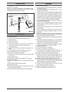
AUTOMATIC EXTRUSION GUNS
651513-11-B
(Extrusion nozzle and retaining nut must be ordered separately.)
2”
31/32”
1-29/32”
2-3/8”
6-11/32”
Figure 1
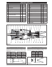
AUTOMATIC AIRLESS SPRAY GUNS
651513-12-B
(TC-XXXX tip must be ordered separately.)
Figure 2
SPECIFICATIONS
Material Inlet . . . . . . . . . . . . . . . . . . . . . . . . . 1/4 - 18 N.P.S.M.
Air Inlet . . . . . . . . . . . . . . . . . . . . . . . . . . . . . . . 1/8 - 27 N.P.T.F. - 1
Diameter . . . . . . . . . . . . . . . . . . . . . . . . . . . . . 2” (50.8 mm)
Length (without nozzle) . . . . . . . . . . . . . . . 6-11/32” (161.1 mm)
Weight . . . . . . . . . . . . . . . . . . . . . . . . . . . . . . . 17 oz. (482 grams)
Mounting Hole Diameter . . . . . . . . . . . . . . 33/64” (13.1 mm)
Maximum Operating Fluid Pressure . . . . 5000 p.s.i. (345 bar)
Minimum Air Pressure Required
@ 2000 p.s.i. (138 bar) Fluid Pressure . 50 p.s.i. (3.4 bar)
DESCRIPTION
The following model guns permit spraying or extruding of
material continuously or intermittently by using spring re-
turn. See chart below for characteristics of each model.
These unit are identical expect spray guns include a spray
guard which retains the TC-XXXX airless spray tip. They in-
clude a stainless steel head, aluminum air cylinder, a 1/4 -
18 N.P.S.M. material inlet, a 1/8 - 27 N.P.T.F. - 1 air inlet and a
needle shroud (17) for prolonged life. The compact design of
either gun allows mounting in a closely con ned area.
Model Material Includes Tips
651513-11-B Heavy Materials 66541-XX
651513-12-B Light Fluids 66504 Cap TC-XXXX
OPERATION
Turn air to “ON” position at supply source. Air must be regu-
lated at 60 p.s.i. (4 bar) to maintain proper performance.
STROKE ADJUSTMENT
For maximum uid ow and tip and needle life;
Turn knurled adjusting screw (23) counterclockwise until
contact is lost between it and (15) nut.
Turn adjusting screw clockwise until contact is again
made with the (15) nut.
Back out adjusting screw approximately 1/4 turn.
Lock (23) adjusting screw in place by tightening (24) nut.
MAINTENANCE
To maintain reliable performance, the gun should be ushed
out with a compatible solvent immediately following each
spray or extrusion period. This will decrease the chance of
material build-up within the gun which will cause poor func-
tioning.
1.
2.
3.
4.