


Page 2 of 4 651513-XX-B (en)
INSTALLATION
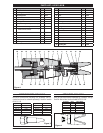
The automatic gun may be mounted on a 1/2” rod and held
in place by (21) set screw.
Connect 1/4 - 18 N.P.S.M. material line to uid inlet as shown.
Connect 3-way valve and air line to 1/8 - 27 N.P.T.F. air inlet
on side of gun body (see gure 3, below).
Air Inlet
Metering Console
Air Motor
Material Outlet
Pilot Operated,
Spring Return
3-Way Valve
Figure 3
DISASSEMBLY
Remove (17) cover.
Loosen (24) nut and remove (23) adjusting screw.
Remove (13) cap.
Remove (14) “O” ring.
Remove (22) spring.
Hold (15) nut and loosen (18) collet nut. CAUTION: Do
not scratch (19) piston rod or burr (18) collet nut.
Loosen (4) cap screw.
Unthread (7) gun body and adapter assembly from (1)
body.
Push (18) collet nut, with (16) piston, out of (1) body.
Unthread (18) collet nut from (19) piston rod.
Remove (2) “O” ring from (16) piston.
Remove (15) nut from (19) piston rod, using wrench ats
on piston rod.
Remove (20) “O” ring.
Remove (9) guard and tip (models 651513-12-B only).
Remove (12) washer.
Remove (11) screw, (25) screw, (27) ball seat and (26) gas-
ket.
Remove the (8) ball and stem assembly.
Remove (10) washer.
Unthread (3) retaining screw and remove from (7) gun
body and adapter assembly.
Remove the two (5) at packings and two (6) packings.
1.
2.
3.
4.
5.
6.
7.
8.
9.
10.
11.
12.
13.
14.
15.
16.
17.
18.
19.
20
.
ASSEMBLY
Replace the (10) washer.
Put the (8) ball and stem assembly into the (7) gun body
and adapter assembly.
Assemble (26) gasket and (27) ball seat into (11) screw,
securing with (25) screw.
Thread (11) screw into (7) gun body and adapter assem-
bly and tighten into body. NOTE: The (9) guard is used on
the spray type models only. When assembling an extru-
sion type gun, insert an extrusion tip assembly instead.
Put the (12) washer inside (9) guard (see note) and thread
into (7) gun body and adapter assembly and tighten.
Put a small amount of grease in hole and on outside di-
ameter of (5 and 6) packings.
Put one of the new (6) packings onto the wire of the
(8) ball and stem assembly (see gure 4, page 3, for cor-
rect installation).
Put the two (5) at packings onto the wire of (8) ball and
stem assembly.
Put the remaining new (6) packing onto the wire of (8)
ball and stem assembly (see gure 4, page 3 for correct
installation).
Slide the (3) retaining screw over the wire of the (8) ball
and stem assembly. Push the packings into the cavity of
the (7) gun body and adapter assembly.
Thread (3) retaining screw into (7) gun body and adapter
assembly.
Push (8) ball and stem assembly into (11) screw until ball
seats against (27) ball seat. Then tighten (3) retaining screw.
Caution: Do not bend (8) ball and stem assembly.
Thread (7) gun body and adapter assembly into (1) body,
until it is in position shown in gure 4, page 3.
Tighten (4) cap screw.
Put (2) “O” ring onto the (16) piston.
Put (20) “O” ring onto the (19) piston rod.
Put (19) piston rod through (16) piston. Thread (15) nut
onto (19) piston rod and tighten, using ats provided.
Thread (18) collet nut into (19) piston rod loosely.
Lubricate (2 and 20) “O” rings and push (16) piston into (1)
body. Do not force into (1) body. CAUTION: Make sure the
(8) ball and stem assembly wire enters the (18) collet nut.
Push the (16) piston until it bottoms in the (1) body.
Push the (16) piston back out o the bottom of (1) body,
approximately 1/32”. NOTE: Make sure (8) ball and stem
assembly is still seated against (27) ball seat.
Tighten (18) collet nut by holding (15) nut. Do not move
piston from position given in step (21).
Replace (22) spring, securing with (13) cap.
Replace (23) adjusting screw and (24) nut.
1.
2.
3.
4.
5.
6.
7.
8.
9.
10.
11.
12.
13.
14.
15.
16.
17.
18.
19.
20.
21.
22.
23.
24.