


651513-XX-B (en) Page 3 of 4
PARTS LIST / 651513-XX-B
Item Description
(size)
(Qty) Part No.
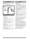
1 Body (1) 91639
2 “O” Ring
(1/8” x 1-3/8” o.d.)
(1) Y325-216
3 Retaining Screw (1) 91473
4 Cap Screw
(#8 - 32 x 1/2”)
(1) Y154-42-C
5 Flat Packing (2) 91472
6 Packing (2) 91471
7 Spray Gun Body and Adapter Assembly (1) 66178
8 Ball and Stem Assembly (1) 66597-3
9 Cap and Guard Assembly
(651513-12-B only)
(includes items 28, 29 and 30)
(1) 66504
10 Washer (1) 91180
11 Screw (1) 92426
12 Washer (1) 91181
13 Cap (1) 91787
14 “O” Ring
(1/16” x 1-1/2” o.d.)
(1) Y325-28
Item Description
(size)
(Qty) Part No.
15 Nut
(#10 - 32)
(1) Y22-110-C
16 Piston (1) 91633
17 Cover (1) 91636
18 Collet Nut (1) 91474
19 Piston Rod (1) 91628
20 “O” Ring
(1/16” x 3/8” o.d. )
(1) Y325-10
21 Set Screw
(1/4” - 28 x 5/16”)
(1) Y23-43
22 Spring (1) 91832
23 Adjusting Screw (1) 91788
24 Nut (1) 91789
25 Screw (1) 92427
26 Gasket (1) 92425
27 Ball Seat (1) 92424
28 Retaining Nut (1) 75807-1
29 Nozzle Guard (1) 91999
30 Feed Ring Wire (1) 91338
28122711548181211615142423
293026102576317192022213
Figure 4
EXTRUSION TIPS AVAILABLE
Extrusion nozzle and retaining nut assembly (not in-
cluded and must be ordered separately). Used on models
651613-11-B.
Tip Number Orifice Diameter
Tip Number Orifice Diameter
66541-03 0.031”
66541-15 0.156”
66541-04 0.046”
66541-17 0.172”
66541-06 0.063”
66541-18 0.187”
66541-09 0.093”
66541-25 0.250”
66541-12 0.125”
66541-37 0.375”
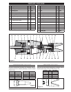
Figure 5
SPRAY TIPS AVAILABLE
Spray tip (must be ordered separately by customer). See tip
chart for desired size. Used on models 651513-12-B.
Tip Number Orifice Pattern Width
TC-1850 0.018” 10”
TC-2140 0.021” 8.5”
TC-2150 0.021” 11.5”
TC-2640 0.026” 9”
TC-2650 0.026” 12”
66504
Figure 6