


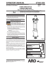
Page 2 of 4 67300-XXX (en)
MATERIAL CODE
[B] = Nitrile [SH] = Hardened Stainless Steel
[C] = Carbon Steel [SS] = Stainless Steel
[D] = Acetal [T] = PTFE
[GFT] = Glass lled PTFE [U] = Urethane
[I] = Iron [UH] = UHMW-PE
[PSH] = Hard Chrome Plated Hardened Stainless Steel
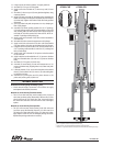
LOWER PUMP DISASSEMBLY
NOTE: All threads are right hand.
Using a wrench on ats of (30) primer rod and a 5/8” wrench
on (33) lock nut, remove (33) lock nut, releasing (32) primer
button and (31) primer plate.
Using a wrench on ats of (10) stud and an 1-1/2” wrench on
(12) nut, remove three (12) nuts and (17) lock washers from
(10) studs.
Remove (6) outlet body, (9) tube and components from (15)
pressure chamber body.
Remove (7) “O” ring from (25) check stop.
Using a wrench on ats of (10) stud, remove three (10) studs.
Using a wrench on ats of (30) primer rod, remove (30) primer
rod from (34) valve rod.
Remove (9) tube and (7) “O” ring from (6) outlet body.
Remove (34) valve rod from (26) plunger, releasing (28) valve
seat and components.
Clamp the (28) valve seat in a vise and remove (36) valve seat
nut, releasing (47) bowed washer, (57) male packing washer,
ve (55) “V” packings and (54) female packing washer.
Remove (1) solvent cup and (3) “O” ring from (2) lower gland.
Remove (26) plunger.
Remove (2) lower gland and (38) “O” ring from (6) outlet body.
Models 67300-J3D: Remove (14) upper gland nut, releasing
(5) bushing and two (64) seals. Remove (18) retaining ring, re-
leasing (64) seal.
Models 67300-C4D: Remove (43) wave spring, (57) male
packing washer, five (55) “V” packings, (54) female packing
washer and (5) bushing from (2) lower gland.
Remove (25) check stop from (15) pressure chamber body.
Remove (21) foot valve body from (15) pressure chamber
1.
2.
3.
4.
5.
6.
7.
8.
9.
10.
11.
12.
13.
14.
15.
16.
body.
Remove (37) retaining ring, releasing (65) “U” cup from (21)
foot valve body.
Remove (44) “O” ring and (22) check valve seat from (15) pres-
sure chamber body.
LOWER PUMP REASSEMBLY
NOTE: All threads are right hand.
Assemble (22) check valve seat and (44) “O” ring into (15) pres-
sure chamber body. NOTE: Assemble (22) check valve seat with
i.d. chamfer up.
Assemble (65) “U” cup into (21) foot valve body, securing with
(37) retaining ring. NOTE: Assemble “U” cup with lips facing up.
Assemble (21) foot valve body into (15) pressure chamber
body.
Assemble (25) check stop assembly into (15) pressure chamber
body.
Assemble (7) “O” ring into (6) outlet body.
Assemble (38) “O” ring into (6) outlet body.
Models 67300-J3D:
a. Assemble one (64) seal into bottom of (2) lower gland,
securing with (18) retaining ring. NOTE: Assemble (64) seal
with lips facing out.
b. Assemble two (64) seals into (2) lower gland, with lips into
gland rst.
c. Assemble (5) bushing into (2) lower gland.
d. Apply PTFE tape to threads of (14) upper gland nut and as-
semble to (2) lower gland.
8. Models 67300-C4D: Assemble (5) bushing, (54) female pack-
ing washer, ve (55) “V” packing, (57) male packing washer and
(43) wave spring. NOTE: Assemble (54) female packing washer
and (55) “V” packing with lips facing out.
9. Apply Loctite 242 to threads of (2) lower gland and assemble
to (6) outlet body.
10. Assemble (26) plunger into (6) outlet body from the bottom
end.
11. Tighten (2) lower gland securely.
17.
18.
1.
2.
3.
4.
5.
6.
7.
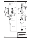
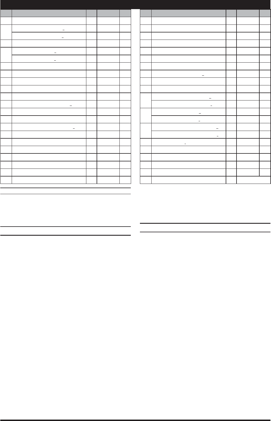
PARTS LIST
Item Description
(size)
(Qty) Part No. Mtl
1 Solvent Cup (1) 92689 [C]
2
Lower Gland
(models 67300-C4D)
(1) 95254 [C]
(models 67300-J3D)
(1) 95327 [C]
3 “O” Ring
(1/16” x 3” o.d.)
(1) Y325-40 [B]
5
Bushing
(models 67300-C4D)
(1) 95255 [D]
(models 67300-J3D)
(1) 95328 [D]
6 Outlet Body (1) 95263 [C]
7 “O” Ring
(1/16” x 3-1/8” o.d.)
(2) Y328-41 [T]
9 Tube (1) 95261 [C]
10 Stud (3) 95351 [C]
12 Nut
(1” - 14)
(3) Y11-16-C [C]
14 Upper Gland Nut
(models 67300-J3D only)
(1) 95326 [C]
15 Pressure Chamber Body (1) 95308-B [I]
17 Lock Washer
(1”)
(3) Y14-100-C [C]
18 Retaining Ring
(2.295” o.d.) (67300-J3D only)
(1) 76243-2 [SS]
21 Foot Valve Body (1) 92682 [SH]
22 Check Valve Seat (1) 96830 [SH]
25 Check Stop (1) 95262 [SS]
26 Plunger (1) 95270-1 [PSH]
27 Valve Seat (1) 95307 [SH]
28 Valve Seat (1) 95267 [SH]
30 Primer Rod (1) 91719 [SH]
Item Description
(size)
(Qty) Part No. Mtl
31 Primer Plate (1) 93599-1 [SS]
32 Primer Button (1) 93598-1 [SS]
33 Lock Nut
(7/16” - 20)
(1) Y171-7-C [C]
34 Valve Rod (1) 95306 [SH]
36 Valve Seat Nut (1) 95269 [C]
37 Retaining Ring
(1.136” o.d.)
(1) Y147-102 [C]
38 “O” Ring
(1/16” x 2-5/8” o.d.)
(1) Y328-37 [T]
43 Wave Spring
(models 67300-C4D only)
(1) 95259 [SH]
44 “O” Ring
(1/8” x 3-1/2” o.d.)
(1) Y328-236 [T]
47 Bowed Washer (1) 95266 [C]
54
Female Packing Washer
(67300-C4D)
(2) 95256 [D]
(models 67300-J3D)
(1) 95256 [D]
55
“V” Packing
(models 67300-C4D)
(10) 95257-4 [UH]
(models 67300-J3D)
(5) 95257-4 [UH]
57
Male Packing Washer
(models 67300-C4D)
(2) 95258 [C]
(models 67300-J3D)
(1) 95258 [C]
64 Seal
(models 67300-J3D only)
(3) 95325 [U]
65 “U” Cup (1) 90911 [GFT]
88 Bleeder Valve Body (1) 97206 [C]
89 Needle Bleed Valve (1) 97207 [C]
Items included in Service Kit 637348-XXD
(continued on page 4)