


LM2350E-X-B
Page4of4
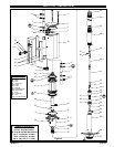
PUMP DISASSEMBLY
NOTE:All threadsarerighthand.Refer tofigure 2(page3).Discon-
nect air supply and relieve all system pressure
prior to servicing.
Carefullyremovethe parts,inspectfordamage, nicksorexcessive wear
and determine if any parts will need replacement.
1. Usinga7/8” wrench,unthreadandremove (11) adapterand(12and
13) ‘‘O” rings, releasing (14) muffler housing.
2. Using a 7/16” wrench, remove (31) nuts.
3. Remove four (1) bolts, (2) upper cap and (3) gasket.
4. Remove (10) cylinder, containing (4) sleeves and (7) spools.
5. Using (1) bolt, push (7) spools and (4) sleeves out “sleeve” end of
(10) cylinder.
6. Remove (18) retaining ring, (19) washer and (21) piston.
7. Remove (25) dowel pin, releasing (23) piston adapter.
8. Remove (3) gasket.
9. Clamp (34) extension tube horizontally in a vise. Unthread and re-
move (30) base, (33) gasket, (28) spring and (26) washer. NOTE:
Remove (29) rod seal only if replacement is necessary.
10. Pull up on (36) piston rod to reveal (38) cotter pin.
11. Remove (38) cotter pin and (37) connecting pin, releasing (36) pis-
ton rod.
12. Using (36) piston rod, push down on (39) connectoruntil it bottoms.
13. Remove (54) retainer ring.
14. Push (55) primer up into (56) primer tube.
15. Lightly wedge aflat bladescrewdriver between(55) primer and(56)
primer tube, so (55) primer unthreads with (56) primer tube.
16. Insert a 5/16” diameter rod thru the cross holes in (56) primer tube
and use the rod to unthread and remove (56) primer tube.
17. Remove (46)spacer,(51)gasket and(52)valveseat from(56)prim-
er tube.
18. Remove (47 - 50) foot valve assembly from (53) primer rod.
19. Remove (47) retaining r ing, releasing (48) “U” cup. NOTE: Do not
remove (49) guide spacer unless replacement is necessary.
20. Remove (45) guide washer.
21. Clamp (40) lower suction tube horizontally in a vise. Unthread and
remove (34) extension tube and (35) gasket.
22. Using a 7/32” diameter rod in thecross hole in (39) connector anda
9/16” wrench on theflats of (41) plunger, unthreadand remove (39)
connector from (41) plunger. NOTE: Do not damage theo.d. of (41)
plunger in any way.
23. Using a 7/16” wrench on flats of (44) adapter and a 1/4” wrench on
flats of (53) primer rod, unthread and remove (53) primer rod.
24. Clamp on flats of (41) plunger and, using a 1/4” wrench on flats of
(44) adapter, unthread and remove(44) adapter, releasing (43) ball
and (42) ball stop.
PUMP REASSEMBLY
NOTE: Thoroughly clean and lubricate all seals and bores with
Shell Gadus S2 U1000upon assembly.Replaceall softparts with
new ones included in the repair kit.Note: Refer to the illustration (figure2,
page 3) for “U” cup lip seal direction.
1. Assemble(42) ballstopand (43)ballinto(41)plunger,securing with
(44) adapter. NOTE:Torque(44) adapterto50 -70 ftlbs (67.8- 94.9
Nm).
2. Assemble(53) primerrodto (44)adapter,using wrenchesonflats to
tighten. NOTE: Torque (53) primer rod to 70 - 100 in. lbs (7.9 - 11.3
Nm).
3. Thread (39) connector to (41) plunger, using a 7/32” diameter rod
thru the cross hole to tighten. NOTE: Tighten (39) connector to 17 -
25 ft lbs (23.0 - 33.9 Nm).
4. Assemble (49) guide spacer and (48) “U” cup into (50) valve body,
securing with (47) retaining ring. NOTE: Assemble chamfered cor-
ner of (49) guide spacer into (50) valve body first.
5. Assemble (45)guide washer and(47 - 50)foot valve assemblyonto
(53) primer rod.
6. Assemble (46) spacer, (51) gasket and (52) valve seat onto (53)
primer rod.
7. Thread (55) primer onto (53) primer rod, securing with (54) retainer
ring.
8. Thread (56) primer tube to (40) lower suction tube and tighten.
NOTE: Torque (56) primer tube to 65 ft lbs (88.1 Nm).
9. Assemble (36) piston rod to (39) connector, securing with (37) con-
necting pin and (38) cotter pin.
10. Assemble (35) gasket and (34) extension tube to (40) lower suction
tubeandtighten. NOTE:Torque(34)extension tubeto65ftlbs(88.1
Nm).
11. Assemble (27) “O” ring, (29) rod seal, (26) washer, (28) spring and
(33) gasketinto(30) baseand assemble(30) baseto(34) extension
tube. Clamp (30) base horizontally in a vise and tighten (34) exten-
sion tube. NOTE: Torque (34) extension tube to 65 ft lbs (88.1 Nm).
12. Push up on (55) primer, exposing (36) piston rod.
13. Assemble (3) gasket to (30) base.
14. Assemble (24)“O”ringto(23)pistonadapter andassemble(23)pis-
ton adapter to (36) piston rod, securing with (25) dowel pin.
15. Replace (20) “U” cups on (21)piston and assemble (21)piston onto
(23) piston adapter, securing with (19) washer and (18) retaining
ring.
16. Replace (5) “O” rings on (4) sleeves and assemble (4) sleeves into
(10)cylinder.NOTE:Assemble eachsleeveintothe endofthe cylin-
der nearest the exhaust hole.
17. Replace (6 and 9) “O” rings and (8) “U” cups on (7) spools and as-
semble (7)spools into (10)cylinder from theopposite end as the(4)
sleeve went in.
18. Assemble (10) cylinder onto the pump, being careful when sliding
over the lips of (20) “U” cups. NOTE: Be sure (3) gasket is seated
properly.
19. Replace (3) gasket on (2) upper cap and assemble (2) uppercap to
(10) cylinder.
20. Assemble (1) bolts to pump, securingwith (31) nuts. NOTE: Torque
(31) nuts to 80 in. lbs (9 Nm).
21. Replace (12 and 13) “O” rings on (11) adapter.
22. Assemble (15) foam liners and(16) edge trims to(14) muffler hous-
ing.
23. Assemble (14) muffler housing to (10) cylinder, securing with (11)
adapter. NOTE: Torque (11) adapter to 80 in. lbs (9 Nm).
TROUBLE SHOOTING
If the pump will not cycle or will not deliver material.
• Becertaintocheckfornon-pumpproblemsincludingkinked,restric-
tiveorpluggedinlet /outlethoseordispensingdevice. Depressurize
the pump system and clean out any obstructions in the inlet/outlet
material lines.
• Check all seals, including track gaskets.
• Check direction of “U” cup lips.
PN 97999-825