


Maintaining Your Server
50 Intel® Server Chassis SC5300 User Guide
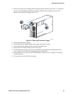
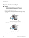
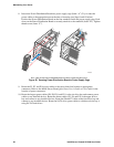
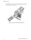
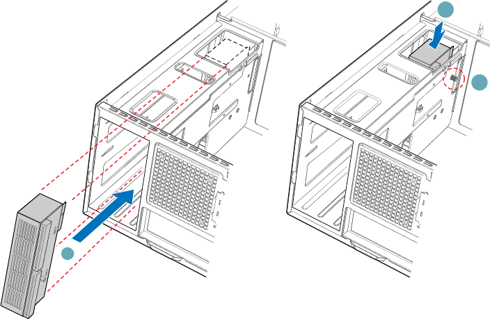
8. Insert new Power Distribution Board into power supply cage (letter “A”). Try to route the
power cables to the appropriate area at the time of insertion (see Steps 9 and 10 below).
Position the Power Distribution Board on the four standoffs inside the power supply cage. Push
down on the Power Distribution Board to securely attach it to the standoffs (letter “B”). Tighten
thumb screw (letter “C”).
A
C
B
TP00693
Note: Cables on back of Power Distribution Board not shown to clarify insertion process.
Figure 58. Securing Power Distribution Board to Power Supply Cage
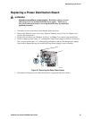
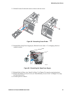
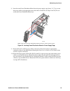
9. Route the P1, P2, and P14 power cables to the server board and connect to appropriate
connectors. Refer to the Intel® Server Board Quick Start User’s Guide or User Guide for the
location of power connectors.
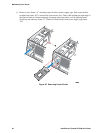
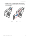
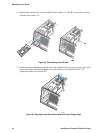
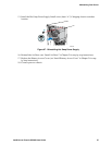
10. Route the longest power cables (P8, P9, P10, and P11) to the six-drive bay and connect power
cables to any installed devices. Route the shorter cables (P3, P4, and P5) to the upper device
bay and connect to any installed devices. Route the P6 and P7 cables to the four-drive bay and
connect to any installed devices. Route the SATA drive power cables to whichever drive bay is
using SATA fixed drives.