


TS Series Conveyors Technical Manual 7610-002-98-29
Issued: 02-15-2006 Revised: N/A
SECTION 1: SPECIFICATION INFORMATION
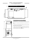
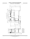
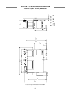
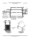
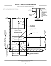
TS-44/TSC-44 DIMENSIONS (CONTINUED)
5
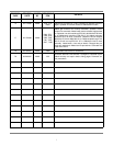
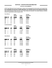
LEGEND FOR TS-44/TSC-44/TS-44GP/TSC-44GP DIMENSIONS:
A = 1/2” IPS incoming water connection, approximately 59-1/2” above the finished floor. Electric heat models only.
B = 1/2” IPS incoming water connection, approximately 59-1/2” above the finished floor. Gas heat models only.
C = Incoming electrical connection point, approximately 59-1/2” above the finished floor. Refer to machine data plate for elec-
trical requirements.
D = 1/2” IPS incoming water connection, approximately 59-1/2” above the finished floor. Gas heat models only, left to right con-
figuration.
E = 1-1/2” IPS drain point connection. If grease trap is required by code, size for 30 gallons per minute flowrate.
F = 1/2” IPS water outlet, approximately 6” above the finished floor. Gas heat models only.
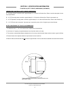
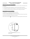
AUXILLARY
RINSE TANK
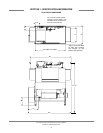
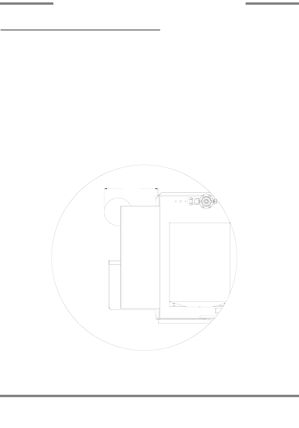
11-1/2"
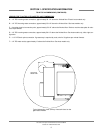
TYPICAL DIMENSION OF GAS MODEL AUXILLARY RINSE
TANK (SCALE 2:1)
Typical dimension of the auxillary rinse tank found on the
gas-heated models.