


TS Series Conveyors Technical Manual 7610-002-98-29
Issued: 02-15-2006 Revised: N/A
SECTION 2: INSTALLATION/OPERATION INSTRUCTIONS
INSTALLATION INSTRUCTIONS
18
VISUAL INSPECTION: Before installing the unit, check the container and machine for damage. A damaged container is an indi-
cator that there may be some damage to the machine. If there is damage to both the container and machine, do not throw away
the container. The dishmachine has been inspected and packed at the factory and is expected to arrive to you in new, undam-
aged condition. However, rough handling by carriers or others may result in there being damage to the unit while in transit. If
such a situation occurs, do not return the unit to Jackson; instead, contact the carrier and ask them to send a representative to
the site to inspect the damage to the unit and to complete an inspection report. You must contact the carrier within 48 hours of
receiving the machine. Also, contact the dealer through which you purchased the unit.
UNPACKING THE DISHMACHINE: Once the machine has been removed from the container, ensure that there are no miss-
ing parts from the machine. This may not be obvious at first. If it is discovered that an item is missing, contact Jackson imme-
diately to have the missing item shipped to you.
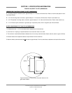
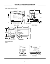
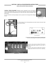
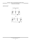
LEVEL THE DISHMACHINE: The dishmachine is designed to operate while being level. This is
important to prevent any damage to the machine during operation and to ensure the best results
when washing ware. The unit comes with adjustable bullet feet, which can be turned using a pair of
channel locks or by hand if the unit can be raised safely. Ensure that the unit is level from side to side
and from front to back before making any connections.
PLUMBING THE DISHMACHINE: All plumbing connections must comply with all applicable local, state, and national plumb-
ing codes. The plumber is responsible for ensuring that the incoming water line is thoroughly flushed prior to connecting it to
any component of the dishmachine. It is necessary to remove all foreign debris from the water line that may potentially get
trapped in the valves or cause an obstruction. Any valves that are fouled as a result of foreign matter left in the water line, and
any expenses resulting from this fouling, are not the responsibility of the manufacturer.
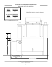
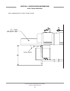
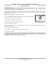
CONNECTING THE DRAIN LINE: The drain for the models covered in
this manual are gravity discharge drains. All piping from the machine to
the drain must be a minimum 1 1/2” NPT and shall not be reduced.
There must also be an air gap between the machine drain line and the
floor sink or drain. If a grease trap is required by code, it should have a
flow capacity of 30 gallons per minute.
WATER SUPPLY CONNECTION: Ensure that you have read the sec-
tion entitled “PLUMBING THE DISHMACHINE” above before proceed-
ing. Install the water supply line (1/2” pipe size minimum) to the dish-
machine line strainer using copper pipe. It is recommended that a water
shut-off valve be installed in the water line between the main supply and
the machine to allow access for service. The water supply line is to be
capable of 25 PSI “flow” pressure at the recommended temperature
indicated on the data plate.
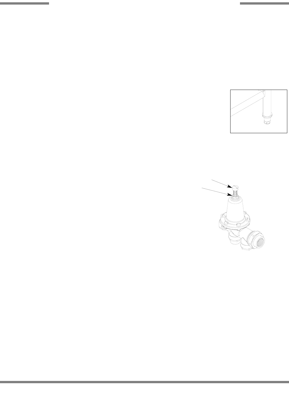
In areas where the water pressure fluctuates or is greater than the recommended pressure, it is suggested that a water pres-
sure regulator be installed. The models covered in this manual do come with water pressure regulators as standard equipment.
Please notify Jackson immediately if this component is not present on your machine.
Do not confuse static pressure with flow pressure. Static pressure is the line pressure in a “no flow” condition (all valves and
services are closed). Flow pressure is the pressure in the fill line when the fill valve is opened during the cycle.
It is also recommended that a shock absorber (not supplied) be installed in the incoming water line. This prevents line hammer
(hydraulic shock), induced by the solenoid valve as it operates, from causing damage to the equipment.
PLUMBING CHECK: Slowly turn on the water supply to the machine after the incoming fill line and the drain line have been
installed. Check for any leaks and repair as required. All leaks must be repaired prior to placing the machine in operation.
GAS CONNECTIONS: Some machines covered in this manual are designed to use gas as an outside source of heat for wash
tank water. The machines come with connections by which an outside source needs to be connected. Connect all incoming gas
lines in accordance with the gas booster manufacturer’s instructions. Ensure that all applicable codes and regulations are
adhered to.
Frame with Adjustable Foot
Incoming Plumbing Connection
Locking nut
Adjusting screw