


13
MCDA1
1
2
3
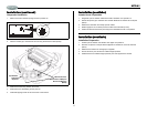
White/Black (-)
Blanco/Negro (-)
Blanc/Noir (-)
White / Blanco / Blanc (+)
Gray/Black (-)
Gris / Negro (-)
Gris / Noir (-)
Gray / Gris / Gris (+)
Violet / Violeta / Violet (+)
+
4
5
6
7
9
8
10
Green / Verde / Vert (+)
Green/Black (-)
Verde/Negro (-)
Vert/Noir (-)
Violet/Black (-)
Violeta/Negro (-)
Violet/Noir (-)
10A
1
1
2
1
1
1
3
1
4
1
5
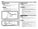
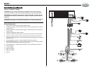
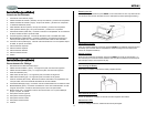
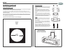
Installation (continued)
Wiring / Cableado / Cablage
IMPORTANT: Incorrect wiring connections can damage the unit. Follow the wiring
instructions carefully, or have the installation handled by an experienced technician.
IMPORTANTE: Una conexión incorrecta de los cables puede dañar la unidad. Siga las
instrucciones del cableado cuidadosamente o haga que un técnico experto realice la
instalación.
IMPORTANT: Des connexions câblage incorrectes peuvent nuire à l'appareil. Suivez les
instructions de câblage avec soin ou faites installer par un technicien expérimenté.
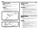
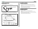
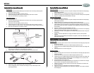
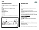
Wiring Connections
1. Connection to the remote control (black cable/connector).
2. Auxiliary input (AUX 1) connectors (yellow cable) - Red is the right channel, and white is
the left channel.
3. Auxiliary input (AUX 2) connectors (black cable) - Red is the right channel, and white is
the left channel.
4. Subwoofer cable (green cable/connector).
5. Front RCA cable (brown cable) - Red is the right channel, and white is the left channel.
6. Rear RCA cable (grey cable) - Red is the right channel, and white is the left channel.
7. Power Antenna (dark blue wire) - Connect to power antenna or amplifier. If not used, tape
bare end of wire.
8. Accessory/Ignition (red wire) - Connect to existing radio wire or radio fuse.
9. Memory/Battery (yellow wire) - Connect to battery or 12 volt power source that is always
alive. The radio will not work if this wire is not connected.
10. Ground (black wire) - Connect to ground terminal or clean, unpainted part of chassis.
11. Left front speaker
12. Left rear speaker
13. Right front speaker
14. Right rear speaker
15. Antenna