05-10324
June 2003
Mounting Instructions
John Deere 4100, 4110 and 4115
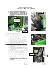
Q. Install right and left floor mats on each side.
R. Remove Slow Moving Vehicle sign and
bracket from tractor seat. Re-mount sign and
bracket using holes located on the back-left
side of cab.
4. ELECTRICAL HOOKUP (All Models)
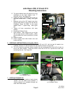
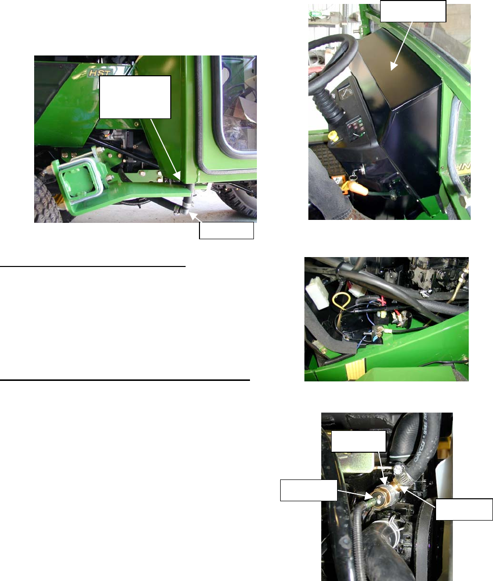
A. Mount #3-17803 Universal Wire Relay
Breaker Kit in the engine compartment area.
Bracket #6-42329 may be used if room
permits. See Figure 4A.
B. Refer to drawing #3-17803 and # 8-14376 for
additional electrical connections and details.
C. Make sure the cab is grounded to frame by
installing cab to ground wire #8-14258.
5. HEATER HOSE HOOKUP (Ref. Drawing #8-14232)
A. Drain coolant from radiator and engine block.
B. Remove temperature sensor from thermostat
housing area.
C. Install aluminum fitting #3-15815 with O-ring
washer #3-16823 into thermostat housing.
See Figure 5C.
D. Re-install temperature sensor into the
aluminum fitting just installed (Step 5C).
E. Install hose to NPT fitting #3-12119 into the
side port of the aluminum fitting.
F. Measure and cut the 5/8” heater hose that
routes (Supply Line) from the left (Driver) side
of the cab to the thermostat-aluminum-hose
nipple fitting. Plastic elbow #3-10282 should
be used at the bottom of the cab tubes. See
Figure 3M.
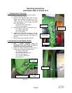
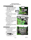
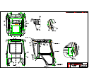
Figure 3M
Figure 4A
Figure 5C
Note 5E
Note 5C
Note 5D
Figure 3P
(
4110 hood shown
)
Note 3P
Isolator
Bushing
#3-16635
N
ote
5
F
Page 5


