


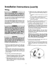
Installation Instructions (cont'd)
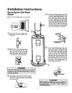
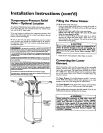
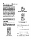
Temperature-Pressure Relief
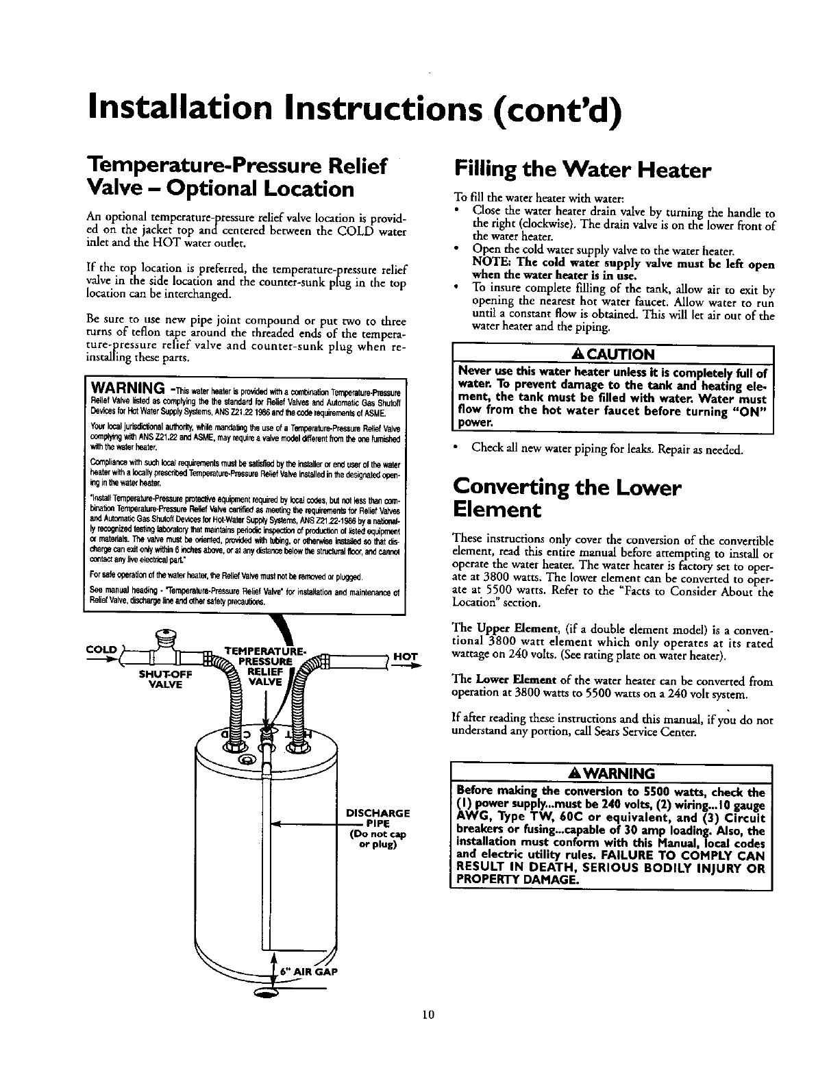
Valve - Optional Location
An optional temperature-pressure relief valve location is provid-
ed on the jacket top andcentered between the COLD water
inlet and the HOT water outlet.
If the top location is preferred, the temperature-pressure relief
valve in the side location and the counter-sunk plug in the top
location can be interchanged.
Be sure to use new pipe joint compound or put two to three
turns of teflon tape around the threaded ends of the tempera-
ture-pressure relief valve and counter-sunk plug when re-
installing these parts.
WARNING -_is *_ter heaterisprovidedwitha combleafi_Temperature-Pressure
ReliefValvelistedascomplyingit_ theelandardferReliefValve_andAutomaticGasShutoff
DevicesferHotWaterSupplySystems,ANS721.221_6 andthecoderequirementsofASME.
YourIcca_jurisdiclfendiauthorby,whilemaeda_ngtheuseofa Tefederatum-Pres_JreReliefVdi_
complyingwi_ANSZ21.22andASME,mayrequireavdi_ modeldifferentfrc_ntheonehJmiSt_d
withthewaterbeater,
C_pliancewithsuch_ reqlerernenfemustbesatisfiedbytheleutellerorenduserofthewater
heaterwithalocallyprescribedTemberthure-PressureRdlefValveina_lledinthedesignatedopen-
leginthewaterhether.
'festdi_Ternperatu_Pre_sureprotectiveeduipmeutrequiredbylocalcodes,butrotlesstbencom-
elnatic_T_Cnberofum-PressureRelfefVak,_certifiedasmeetingthereqleremen_sto_Rofed
a,xiAutomabeGasShutoffDe_cesforHof-WaterSupp_8y_ras, N_S2:2122-19_bya national*
lyrecognizedtestingkCut_ry thatrn_ntelespededicinspeci_ofproductionoflistedequipment
matedais._ valvemustbebeentbe,providedwithte_ng,orother*tseinstut_so_at dis-
dlargecanexitonlyv,shin6 lechesof_ove,or_ anyd_tencebdowtbesttu_terdifloor,and_
conlautany_vedect_.alpar_"
Forsafeppertefe_oftbewa_ heater,1heReliefValvemuutnotberemovedorplugged.
Seemanualheading. "T#raperelure*PressureReliefValve'fe,"i_stel_le_acidmaintenanceof
ReliefValve,dischargelineanduthersafelypreceubens.
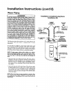
COLD TEMPERATURE-
PRESSURE
SHUTOFF
VALVE
DISCHARGE
(Do not cap
or plug)
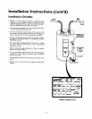
Filling the Water Heater
To fill the water heater with water:
Close the water heater drain valve by turning the handle to
the right (clockwise). The drain valve is on the lower front of
the water heater.
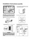
Open the cold water supply valve to the water heater.
NOTE: The cold water supply valve must be left open
when the water beater is in use.
To insure complete filling of the tank, allow air to exit by
opening the nearest hot water faucet. Allow water to run
until a constant flow is obtained. This will let air out of the
water heater and the piping.
I A CAUTION 1
Never usethis water heater unlessit iscompletely full of |
water. To prevent damage to the tank and heating ale- |
ment, the tank must be filled with water. Water must
flow from the hot water faucet before turning "ON" |
power. |
Check all new water piping for leaks. Repairas needed.
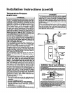
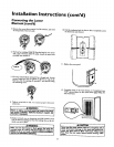
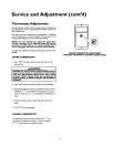
Converting the Lower
Element
These instructions only cover the conversion of the convertible
element, read this entire manual before attempting to install or
operate the water heater. The water heater is factory set to oper-
ate at 3800 watts. The lower element can he converted to oper-
ate at 5500 watts. Refer to the "Facts to Consider About the
Location" section.
The Upper Element, (if a double element model) is a conven-
tional 3800 watt element which only operates at its rated
wattage on240 volts. (Seerating plateon waterheater).
The Lower Element of the water heater can be converted from
operation at 3800 watts to 5500 watts on a 240 volt system.
If after reading these instructions and this manual, if you do not
understand any portion, call Sears Service Center.
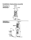
AWARNING
Before making the conversion to 5500 watts, check the
(I) power supply...must be 240 volts, (2) wiring...10 gauge
AWG, Type TW, 60C or equivalent, and (3) Circuit
breakers or fusing_capable of 30 amp loading. Also, the
installation must conform with this Manual, local codes
and electric utility rules. FAILURE TO COMPLY CAN
RESULT IN DEATH, SERIOUS BODILY INJURY OR
PROPERTY DAMAGE.
IR GAP
10