


TH-K2AT/K2E/K2ET
40
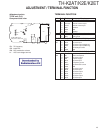
ANT
ANT
ANT
MIC
Encoder
[MENU]
Encoder
[MENU]
[MENU]
LCD
LCD
VR6
VR5
Write
Write
Write
Check
Check
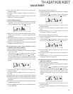
By tuning the
VR6, adjust
the modulation
wave until
if becomes the
square wave.
4.2kHz
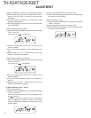
According to the
larger +, –.
0.5W ±0.05W
0.8A or less
All segments
are lighted.
■■■■■■■■■
4 to 6 seg-
ments are
lighted.
■■■■ ~
■■■■■■
±0.1kHz
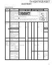
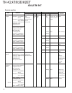
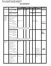
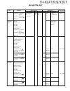
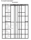
Item Condition
Measurement Adjustment
Specifications/
Test equipment Unit
Terminal
Unit
Parts Method
Remarks
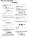
Low power
3.Battery
terminal
reference
voltage
Adjust/
Check
4.DCS
modulation
balance
5.MAX DEV
8) LCD display: P13C,
Frequency: 145.000MHz
PTT: ON
9) LCD display: P13H,
Frequency: 145.995MHz
PTT: ON
Switch to Adjustment mode
and carry out the operations
for adjustment item B.
(Refer to page 28)
TX power: Low
1)LCD display: BAT
Frequency:145.000MHz
(E, E3)
Frequency:146.000MHz
(K, K2, M, M2)
PTT: ON
Battery terminal voltage: 7.5V
To exit from the Adjustment
Mode, turn the transceiver
power OFF and then ON.
2)Frequency:145.000MHz
(E, E3)
Frequency:146.000MHz
(K, K2, M, M2)
PTT: ON
Battery terminal voltage: 6.4V
Switch to Adjustment mode
and carry out the operations
for adjustment item L.
(Refer to page 32)
Detector: +P, –P
HPF: OFF LPF: 3kHz
De-emphasis: OFF
TX power: Low
1)LCD display: DCS.BAL
Frequency:145.000MHz
(E, E3)
Frequency:146.000MHz
(K, K2, M, M2)
PTT: ON
To exit from the Adjustment
Mode, turn the transceiver
power OFF and then ON.
MIC terminal input
AG: 1kHz/80mV
Detector: +P, –P
HPF: OFF LPF: 15kHz
De-emphasis: OFF
TX power: Low
Power meter
Am meter
DC power supply
DVM
Linear detector
Oscilloscope
Linear detector
AG
Oscilloscope
TX-RX
(A/3)
TX-RX
(A/3)
ADJUSTMENT
(Adjust the output voltage from DC power supply until the voltage at the
battery terminal becomes 7.5V while the transceiver is transmitting.)
(Adjust the output voltage from DC power supply until the voltage at the
battery terminal becomes 6.4V while the transceiver is transmitting.)