


TK-2102G
3
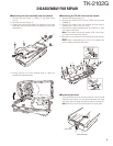
REALIGNMENT
1. Modes
User mode
PC mode
PC test mode PC tuning mode
Data programming mode
Mode Function
User mode For normal use.
PC mode
Used for communication between the trans-
ceiver and PC.
Data programming
mode
Used to read and write frequency data and
other features to and from the transceiver.
PC test mode
Used to check the transceiver using the PC.
This feature is included in the FPU.
2. How to Enter Each Mode
Mode Operation
User mode Power ON
PC mode Received commands from PC
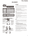
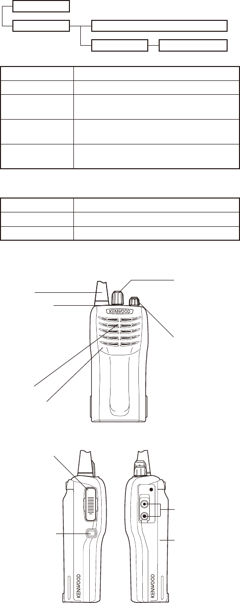
3. Getting Acquainted
4. PC Mode
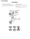
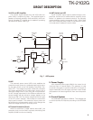
4-1. Preface
The transceiver is programmed by using a personal com-
puter, a programming interface (KPG-22/22A), USB adapter
(KCT-53U) and programming software (KPG-55D (ver.4.00 or
later)).
The programming software can be used with a PC. Fig-
ure 1 shows the setup of a PC for programming.
4-2. Connection Procedure
1. Connect the transceiver to the personal computer with
the interface cable and USB adapter (when the interface
cable is KPG-22A, the KCT-53U can be used.).
Notes:
• You must install the KCT-53U driver in the computer to
use the USB adapter (KCT-53U).
• When using the USB adapter (KCT-53U) for the fi rst time,
plug the KCT-53U into a USB port on the computer with
the computer power ON.
2. When the POWER is switched on, user mode can be en-
tered immediately. When the PC sends a command, the
transceiver enters PC mode.
When data is transmitting from the transceiver, the red
LED lights.
When data is received by the transceiver, the green LED
lights.
Notes :
• The data stored in the personal computer must match
the Model Name when it is written into the EEPROM.
• Do not press the [PTT] key during data transmission or
reception.
• Change the transceiver to PC mode, then attach the in-
terface cable.
4-3. KPG-22/KPG-22A Description
(PC programming interface cable : Option)
The KPG-22/22A is required to interface the transceiver
with the computer. It has a circuit in its D-sub connector
(KPG-22: 25-pin, KPG-22A: 9-pin) case that converts the RS-
232C logic level to the TTL level.
The KPG-22/22A connects the SP/MIC connector of the
transceiver to the RS-232C serial port of the computer.
4-4. KCT-53U Description (USB adapter : Option)
The KCT-53U is a cable which connects the KPG-22A to
a USB port on a computer.
When using the KCT-53U, install the supplied CD-ROM
(with driver software) in the computer. The KCT-53U driver
runs under Windows 2000 or XP.
Speaker
Speaker/
microphone
jacks
Microphone
Antenna
PTT (Push-To-
Talk) switch
Press, then
speak into the
microphone to
call a station.
Release to
receive.
Monitor key
Press and hold to
turn the squelch
OFF. You will
hear background
noise. Release
to turn the
squelch back ON.
LED indicator
Lights red while
transmitting.
Lights green while
receiving a signal.
Flashes red when
the battery voltage
is low while
transmitting.
Power switch/
Volume control
Turn clockwise
to switch ON the
transceiver. To
switch OFF the
transceiver, turn
counterclockwise
until a click
sounds. Rotate
to adjust the
volume level.
Channel
selector
Rotate to select
channels 1 ~ 16.
Battery pack
(KNB-15A)