


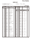
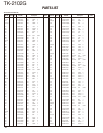
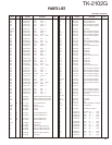
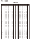
TK-2102G
6
CIRCUIT DESCRIPTION
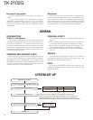
1. Frequency Confi guration
The receiver utilizes double conversion. The first IF is
38.85MHz and the second IF is 450kHz. The fi rst local oscil-
lator signal is supplied from the PLL circuit.
The PLL circuit in the transmitter generates the neces-
sary frequencies. Fig. 1 shows the frequencies.
2. Receiver
The receiver is double conversion superheterodyne, de-
signed to operate in the frequency range of 150 to 174MHz.
The frequency confi guration is shown in Fig. 1.
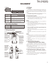
1) Front-end RF Amplifi er
An incoming signal from the antenna is applied to an RF
amplifier (Q203) after passing through a transmit/receive
switch circuit (D102 and D103 are off) and a band pass fi lter
(L208, L209 and L210). After the signal is amplifi ed (Q203),
the signal is filtered through a band pass filter (L203 and
L214) to eliminate unwanted signals before it is passed to
the fi rst mixer. Band pass fi lters (L208, L209, L210, L203
and L214) have varactor diodes (D203, D204, D205, D202
and D201).
The voltage of these diodes are controlled by to track the
MPU (IC403) center frequency of the band pass fi lter. (See
Fig. 2)
2) First Mixer
The signal from the RF amplifi er is heterodyned with the
fi rst local oscillator signal from the PLL frequency synthe-
sizer circuit at the fi rst mixer (Q202) to create a 38.85MHz
fi rst intermediate frequency (1st IF) signal. The fi rst IF signal
is then fed through two monolithic crystal filters (MCFs :
XF200) to further remove spurious signals.
3) IF Amplifi er
The fi rst IF signal is amplifi ed by Q201, and then enters
IC200 (FM processing IC). The signal is heterodyned again
with a second local oscillator signal within IC200 to create
a 450kHz second IF signal. The second IF signal is then fed
through a 450kHz ceramic fi lter (CF200) to further eliminate
unwanted signals before it is amplifi ed and FM detected in
IC200.
4) AF Amplifi er
The recovered AF signal obtained from IC200 is amplifi ed
by IC300 (1/4), fi ltered by the IC300 low-pass fi lter (2/4) and
IC300 high-pass filter (3/4) and (4/4), and de-emphasized
by R303 and C306. The AF signal is then passed through a
WIDE/NARROW switch (Q303). The processed AF signal
passes through an AF volume control and is amplifi ed to a
suffi cient level to drive a loud speaker by an AF power am-
plifi er (IC302).
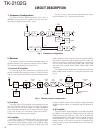
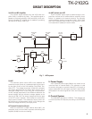
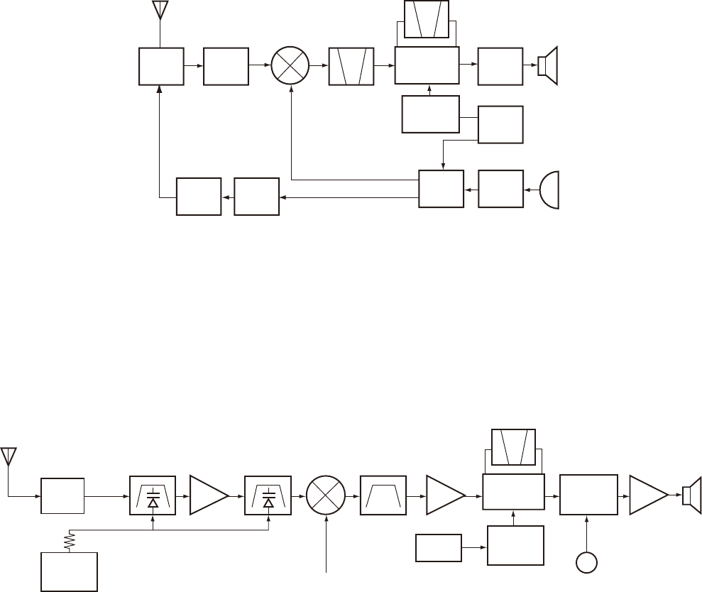
Fig. 1 Frequency confi guration
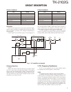
Fig. 2 Receiver section confi guration
ANT
ANT SW
RF
AMP
MCF
CF
IF SYSTEM
AF
AMP
RX
TX
PA
AMP
TX
AMP
PLL
VCO
MIC
AMP
TCXO
X3
multiply
38.85MHz
450kHz
38.4MHz
12.8MHz
SP
MIC
ANT
D102, D103
BPF
RF AMP
Q203
BPF
MIXER
Q202
MCF
XF200
IF AMP
Q201
CF200
IF, MIX, DET
IC200
AF AMP
LPF, HPF
IC300
AF PA AMP
IC302
SP
X3
multiply
Q1
TCXO
1st Local OSC
(PLL)
ANT SW
APC
TUNE
IC403
MPU
WIDE/NARROW SW
Q303