


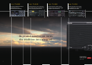

Transmit
ANT
1 2 3 4
MAIN RX ANT
OFF
MAIN
BAND
RECEIVER
SUB
BAND
RECEIVER
OFF
ON
ON
AT
RX
TX
MAIN BAND
ANT Selector
SUB BAND
ANT Selector
Transmission Unit
RX OUT RX IN
SUB RX ANT
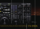
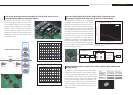
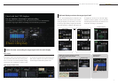
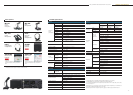
3rd order TX IMD 14.2MHz / 200W
SPAN 10 kHz10 dB / div
-10
-50
-70
-90
-30
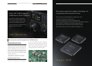
FET attributes. Further, you can realize Kenwood’s
distinctive tone by amplifying the clean modulated
signal produced by DSP with an ampli er that ex-
hibits excellent linearity.
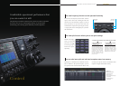
The device uses POWER MOSFET VRF150MP,
which runs at 50V, with push-pull. You can obtain a
high, stable output of 200 W on all bands. You can
achieve superior IMD properties by pursuing bias
and matching conditions in order to fully exploit the
High reliability design promises stable operation at 200W
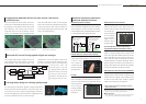
The built-in automatic antenna tuner is a preset
type that covers amateur band frequencies rang-
ing from 160m~6m, and can be switched in on
receive too. The tuner is capable of rapid QSY
based on instantaneous band change, using a relay
system that is known for high-speed operations.
The relay, inductors, and coil use large-sized com-
ponents that are able to bear the 200 W output.
Built-in automatic antenna tuner capable of high-speed operation
Cooling is very important to obtain a stable output
of 200 W. Heat dissipation ef ciency is increased
in the TS-990S through a large n-type aluminium
heat sink. An independent variable-speed fan is
provided for the switching power supply, final
unit, and antenna tuner, cooling each unit with a
suf cient air supply. The switching power supply
and the nal unit have twin cooling fans. Noise is
reduced by controlling the fan speed according to
the temperature.
Cooling system to send a suffi cient volume of air to each unit
Operating stably even when continually working over long periods of time,
such as in competitions.
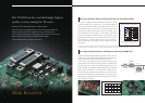
Transmitter performance,
featuring high-scale specifi cations,
can withstand long periods of operation at full power.
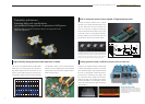
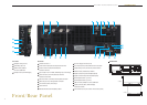
It is outfi tted with four antenna terminals, which can be set independently
on amateur bands, whether main band or sub band. The reception input
and output terminals can be used for reception dedicated antennas,
antenna output for external reception devices, and external BPF
connections. It is usable with either the main band or the sub band.
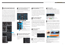
Thermal simulation example
To dissipate the heat of the 200 W fi nal, we
used swage fi ns instead of the conventional
extruded aluminum fi ns. Using CAE analysis
we designed the optimal fi n shape and size
for heat dissipation.
10
Transmission unit /cooling
HF/50MHz TRANSCEIVER TS-990S