


7
1st Mixer
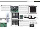
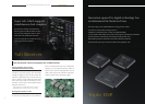
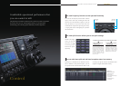
The transceiver uses a down-conversion method
for all amateur band reception, and features five
types of High-IP roofing filter. Narrow bandpass
widths selectable are 500 Hz and 270 Hz for CW
operation, 2.7kHz for SSB and 6kHz and 15kHz,
which are suitable for AM/FM. These filters are
automatically selected in tandem with DSP-based
nal bandpass settings. Of course, manual switch-
ing is possible as well.
The newly developed narrow-band High-IP roofi ng fi lter shows its true
value by cutting adjacent unwanted signals
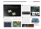
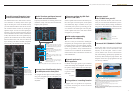
The standard equipment includes a TCXO (Temperature-
Compensated crystal Oscillator), which stabilizes frequen-
cies at ±0.1ppm as the standard signal source. Unlike OCXO
(Oven Controlled crystal Oscillator), which requires warm-up
time, this device can start up quickly even from the power-off
position, while maintaining a high level of stability. It is in
compliance with European energy-saving standard Lot6.
Power consumption in stand-by energy-saving mode is less
than 0.5 W. A BNC connector on the rear panel provides
10MHz reference I/O.
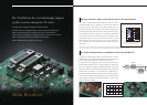
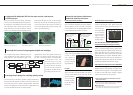
The TS-990S Local Oscillator Circuit is an independent
con guration that combines the main receiver and VCO
Frequency Division/DDS Direct, the sub-receiver and
DDS Direct, and the transmitter and conventional PLL,
with the targeted signal system. The newly developed
VCO frequency division format is used for the 1st lo-
cal oscillator of the main receiver. The device achieves
favourable C/N characteristics that rival the DDS direct
format, and relatively spurious-free local oscillation
signals that are characteristic of the PLL format, by
oscillating and dividing the VCO at higher frequencies
than the intended frequency. It is possible to convert it
to 1st IF in a pure state without leaking the target signal
as noise by reducing static noise from the local oscilla-
tor and increasing the C/N ratio.
You can realize high C/N levels by dividing high frequencies using
the newly developed VCO frequency division 1st local oscillator
Comes equipped with ±0.1ppm TCXO, which combines high stability and
energy saving
DDS IC AD 9951
Main receiver 1st Local Oscillator C/N main receiver characteristic
example (20m/160m)
TS-990S MAIN Local OSC C/N
Phase Noise [dBc/Hz]
Offset Frequency [Hz]
100
-160
-150
-140
-130
-120
-110
-100
-90
-80
-70
-60
-50
-40
-30
-20
-10
0
1,000 10,000 100,000
14.1MHz
1.83MHz
82.78
92.48MH
96.48
107.48MH
115.48
128.992MH
127.48
138.992MH
PLL PLL
AMP
AMP
Divider
1/N
Main reception unit
1st local oscillator block diagram
DDS
1.8/3.5/5M
7M
14/18/21/24M
...
N=10
...
N=8
...
N=4
(other than these,
DDS Direct)
through
through through
0/6/12/18dB
270Hz
500Hz
6kHz
15kHz
2.7kHz
1st Mixer
Roofing
Filters
RF BPF
ATT
Pre Selector
Pre Amp Post Amp
500Hz
6kHz
TS-990S MAIN BAND FRONT-END
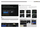
Roofi ng fi lter-characteristic example BW=500Hz
Roofi ng fi lter-characteristic example BW=270Hz
CH1 B/R log MAG
CH2 B/R log MAG
IF BW 100 Hz SWP 8.6 sec
SPAN 2 kHz
10 dB/ REF 0 DB
10 dB/ REF 0 DB
SPAN 100 kHz
CH1 B/R log MAG
CH2 B/R log MAG
IF BW 100 Hz SWP 8.6 sec
SPAN 3.5 kHz
10 dB/ REF 0 DB
10 dB/ REF 0 DB
SPAN 100 kHz
Mode Phantom load Start-up time
Stand-by
power saving
Or Less
0.5W
Approx.
40 seconds
Normal
Approx.
20W
Approx.
5 seconds
Main receiver
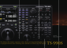
HF/50MHz TRANSCEIVER TS-990S