Owner’s Manual 13
External Equipment Connections
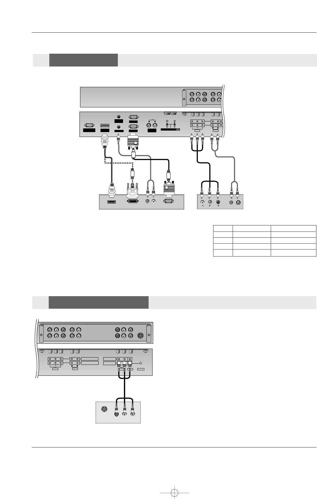
How to connect
Use the set’s COMPONENT (Y, PB, PR) INPUT, RGB or HDMI/DVI jack for
video connections, depending on your set-top box connector. Then, make the
corresponding audio connections.
How to use
1. Turn on the digital set-top box. (Refer to the owner’s manual for the digital set-
top box.)
2. Use MULTIMEDIA on the remote control to select RGB, HDMI, Component 1
or Component 2 source.
- To watch digitally broadcast programs, purchase and connect a digital set-top box.
RS-232C INPUT
(CONTROL/SERVICE)
AUDIO AUDIO
LR
REMOTE
CONTROL
AUDIO INPUT
RGB INPUT
HDMI/
DVI(VIDEO)
RGB OUTPUT
CO
CO
AUDIO
VIDEO
RL
VARIABLE
AUDIO OUT
EXTERNAL SPEAKER
R
L
RGB-DTV OUTPUT
(R) AUDIO (L)
DVI-DTV OUTPUT
HDMI OUTPUT
B
R
(R) AUDIO (L)
Digital Set-top Box
or
or
Signal
480i
480p
720p
1080i
Component 1/2
Yes
Yes
Yes
Yes
RGB, HDMI
No
Yes
Yes
Yes
DTV
DTV
Setup
Setup
The set has a special signal output capability which allows you to
hook up a second set.
Connect the second set to the set’s MONITOR OUTPUT. See the
Operating Manual of the second set for further details regarding that
device’s input settings.
NOTE
• Component, RGB, HDMI input sources cannot be used for Monitor
out.
AUDIO
VARIABLE
AUDIO OUT
S-VIDEO
COMPONENT INPUT 2
COMPONENT INPUT 1
AUDIO
VIDEO
RL
AUDIO
VIDEO
R
MONITOR OUT
A/V INPUT
L
MONO
S-VIDEO
IN
(R) AUDIO (L) VIDEO
Monitor Out
Monitor Out
Setup
Setup
U514Aen 98/1/20 1:25 AM Page 13


