


2
gram most suited to your brand of radio or other device. If your device
manual indicates an RS-232 connection (i.e., a computer), remove the
resistor and diode and connect using Wiring Diagram B. Most other
connection types (TTL; NMEA + and NMEA –; differential) will re-
quire Wiring Diagram A.
Recommended Tools and supplies
Recommended tools for this job include: wire pliers or wire stripper and a
wire cutter. Required supplies for this job include: two gray (18 gauge) or
blue (16 gauge) wire nuts and electrical tape. Supplies are not included.
Wiring Diagram "A"
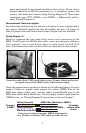
Begin by stripping the wire ends of the device you're connecting to the
M68i. (You'll notice the M68i's data cable comes pre-stripped, with wire
ends exposed.) Use a pair of wire pliers to strip about 1/4-inch (6.35
mm) of insulation from each of the radio's or other device's data wires.
Strip the ends of the VHF radio's data wires. Connect them to the pre-
stripped wires of the M68i's data cable (shown right).
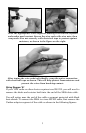
Twist the exposed wires together as shown in the following figures. If you're
using a Uniden or similar radio, connect the radio's NMEA Wire to the
M68i data cable's yellow wire, and the radio's Ground/Shield wire to the
M68i data cable's black shield wire. If you're using another radio brand or
NMEA device, see Wiring Diagram B instructions at the end of page 3.
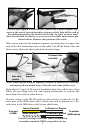
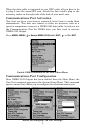
Com port wiring to transmit NMEA information
to a Uniden or similar VHF radio or other device.
Ground/Shield or NMEA –
To Uniden
radio or other
device
Com port
to M68i
Yellow (Transmit)
NMEA Wire (Receive) or NMEA +
Shield (Ground)