


Page 2 For technical questions, please call 1-800-444-3353. SKU 94822
Read the ENTIRE IMPORTANT SAFETY
INFORMATION section at the beginning of this
document including all text under subheadings
therein before set up or use of this product.
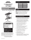
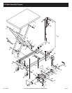
The Hydraulic Lift Table requires some assembly after
you unpack it.
Front
Wheels
(47)
Lock Nuts (14)
Washer (15)
Bushing (48)
Hex Bolts (16)
Figure 1
1. First, set aside the hardware needed to install the Front
Wheels (47). The hardware includes the Hex Bolts (16),
Lock Nuts (14), Washers (15), and Bushings (48).
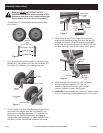
Front Wheel
(47)
Wheel
Frame
Washer (15)
Wrench
Lock Nut (14)
Figure 2
2. Turn Lift Table on its side. Slide Bushing through center
hole in the Front Wheel. Then set Front Wheel in the
wheel frame of the Base Assembly (17). Slide the Hex
Bolt through the Washer, wheel frame and Bushing.
Use a wrench (sold separately) to fasten Lock Nut onto
Hex Bolts, until the Front Wheel is secured into place.
3.
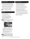
Lifting Pedal
Connector
(30a)
Lifting
Pedal
(27)
Bolt (29)
Wrench
Figure 3
Slide Lifting Pedal (27) into Pedal Connector (30a),
aligning the installation holes. Then slide the Bolt (29)
through the Washer (15) and through the installation
holes. Use the wrench to fasten the Lock Nut (12) over
the Bolt, securing Lifting Pedal in place. See Figure 3.
4.
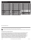
Handle
(21)
Bolt (20)
Base
Assembly
(17)
Wrench
Figure 4
Slide the ends of the Handle (21) into the handle
slots on the Base Assembly (17). Use the
wrench to tighten the Bolts (20) until Handle is
securely fastened in place. See Figure 4.
5. WARNING! After assembly, try out the Lift Table to make
sure it is functioning properly before using it to lift a load.
Assembly Instructions