


35
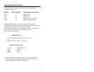
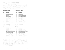
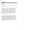
Pin Assignments for the MCA951 (DEC9S)
Located on the MCA is a 9-pin female D-type connector used to connect the
MCA to the host device. The output signals on the 9-pin host end of the MCA
are dependent upon which version of the scanner that is being used. The
following is a list of the pin assignments for the different versions:
Version “9” (OCIA) Version “11” (46XX)
Pin Function Pin Function
1 OCIA Shield Ground 1 Shield Ground
2 RDATA 2 RS-232 Transmit Output
3 RDATA Return 3 RS-232 Receiver Input
4 Clock Out 4 IBM 4680 -B
5 Power/Signal Ground 5 Power/Signal Ground
6 Clock Out Return 6 IBM 4680 +A
7 Clock In Return 7 Clear to Send Input
8 Clock In 8 Request to Send Output
*9 +5VDC Power to Scanner *9 +5VDC Power to Scanner
Version “14” (232) Version “15” (LTPN)
Pin Function PinFunction
1 Shield Ground 1 Shield Ground
2 RS-232 Transmit Output 2 RS-232 Transmit Output
3 RS-232 Receiver Input 3 RS-232 Receive Input
4 Data Terminal Ready Input 4 Light Pen Source (+5V Input)
5 Power/Signal Ground 5 Power/Signal Ground
6 Data Set Ready Output 6 Light Pen Data (Output)
7 Clear to Send Input 7 Clear to Send (Input)
8 Request to Send Output 8 Request to Send (Output)
9 +5VDC Power to Scanner *9 +5VDC Power to Scanner
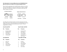
*When the host supplies power to the scanner, this is the pin assignment for
the +5VDC for the scanner. If, in the application, the host device will supply
the power necessary for the scanner, reposition an internal jumper within the
MCA and plug the 4 position ground jumper to the power supply connector for
FCC and ESD purposes. (Refer to Scanner Installation: Powered by
External Power Supply page 5).