40
List of fault displays
Fault
Stall prevention stop
The output frequency has dropped to 1Hz as a
result of deceleration due to the excess motor load.
Reduce the load. (Check the Pr. 22 Stall prevention operation level
setting.)
Brake transistor alarm
detection
A fault has occurred in the brake circuit, such as a
brake transistor breakage.(In this case, the
inverter must be powered off immediately.)
Replace the inverter.
Output side earth (ground)
fault overcurrent at start
∗2
An earth (ground) fault has occurred on the
inverter's output side (detected only at a start).
Remedy the ground fault portion.
Output phase loss
One of the three phases (U, V, W) on the inverter's
output side (load side) has been lost during
inverter operation.
y Wire the cables properly.
y If the motor capacity is smaller than the inverter capacity,
choose the inverter and motor capacities that match.
y If the motor is coasting, stop the motor, then input a start
command. Alternatively, use the automatic restart after
instantaneous power failure/flying start function.
External thermal relay
operation ∗2
The external thermal relay connected to the OH
signal has been activated.
y Reduce the load and operate less frequently.
y Even if the relay contacts are reset automatically, the inverter
will not restart unless it is reset.
Option fault
Installation of a communication option has been
attempted while the operation is restricted with the
password lock (Pr. 296 Password lock level = "0 or
100").
y To apply the password lock when installing a communication
option, set Pr.296 Password lock level ≠ "0, 100."
y If the problem still persists after taking the above measure,
contact your sales representative.
Communication option
fault
A communication error has occurred on the
communication line of the communication option.
y Check the settings of the option functions.
y Connect the built-in option securely.
y Check the connections of the communication cables.
y Connect terminating resistors correctly.
Option fault
A fault, such as a contact fault, has occurred at the
contactor of the inverter or the plug-in option. The
setting of the switch on the plug-in option, which is
for manufacturer setting, has been changed.
y Connect the plug-in option securely.
y Take measures against noises if there are devices producing
excess electrical noises around the inverter.
If the situation does not improve after taking the above
measure, please contact your sales representative.
y Set the switch on the plug-in option, which is for manufacturer
setting, back to the initial setting. (Refer to the Instruction
Manual of each option.)
Parameter storage
device fault
Operation of the component where parameters
are stored (control circuit board) has become
abnormal.
Please contact your sales representative.
When performing parameter writing frequently for
communication purposes, set "1" in Pr. 342 Communication
EEPROM write selection to enable RAM write. Note that powering
OFF returns the inverter to the status before RAM write.
Internal board fault
The control circuit board and the main circuit
board do not match.
Please contact your sales representative.
(For parts replacement, consult the nearest Mitsubishi FA
Center.)
PU disconnection
y A communication error has occurred between
the PU and the inverter.
y The communication interval has exceeded the
permissible time period during RS-485
communication via the PU connector.
y The number of communication errors has
exceeded the number of retries.
y Connect the parameter unit cable securely.
y Check the communication data and communication settings.
y Increase the Pr. 122 PU communication check time interval
setting, or set "9999" (no communication check).
Retry count excess ∗2
Operation restart within the set number of retries
has failed.
Eliminate the cause of the error preceding this error indication.
CPU fault
An error has occurred in the CPU and in the
peripheral circuits.
y Take measures against noises if there are devices producing
excess electrical noises around the inverter.
y Check the connection between the terminals PC and SD. (E6/
E7)
y If the situation does not improve after taking the above
measure, please contact your sales representative.
Brake sequence fault ∗
2
A sequence error has occurred while the brake
sequence function (Pr.278 to Pr.283) is valid.
Check the parameter setting and check the wiring.
Inrush current limit
circuit fault
The resistor of the inrush current limit circuit has
overheated.
Configure a circuit where frequent power ON/OFF is not
repeated.
If the situation does not improve after taking the above
measure, please contact your sales representative.
Analog input fault
A voltage (current) has been input to terminal 4
when the setting in Pr. 267 Terminal 4 input selection
and the setting of voltage/current input switch are
different.
Give a frequency command by a current input or set Pr.267
Terminal 4 input selection, and set the voltage/current input switch
to voltage input.
USB communication
fault
The communication has been broken for Pr. 548
USB communication check time interval.
y Check the Pr.548 USB communication check time interval setting.
y Check the USB communication cable.
y Increase the Pr.548 USB communication check time interval
setting, or set "9999."
Internal circuit fault An internal circuit fault has occurred. Please contact your sales representative.
∗1 Resetting the inverter initializes the internal cumulative heat value of the electronic thermal relay function.
∗2 This protective function is not available in the initial status.
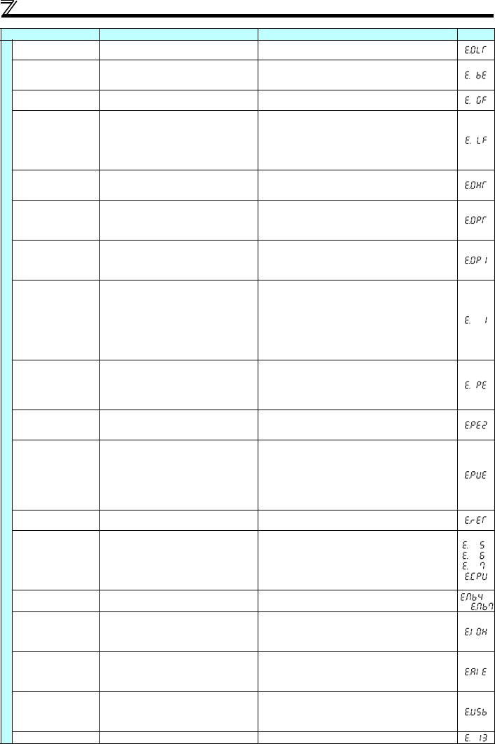
Function Name Description Corrective action Display
to


