


19
Wiring
INSTALLATION AND WIRING
2
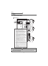
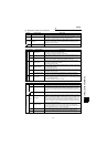
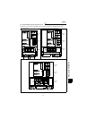
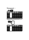
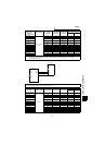
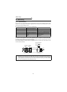
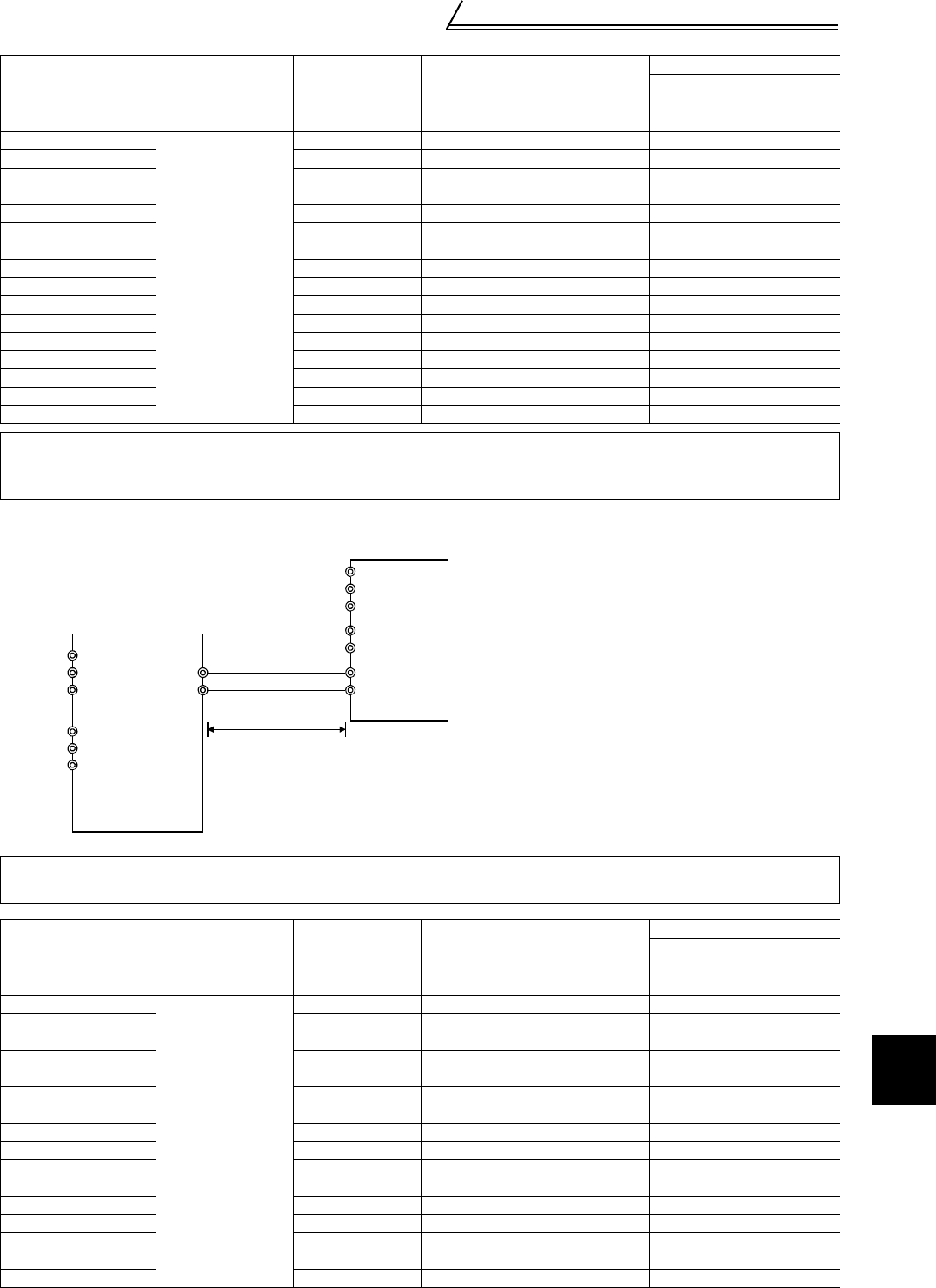
3) Connection of power regeneration common converter and inverter
Power
Regeneration
Common
Converter Model
Terminal Name
Terminal
Screw Size
Tightening
Torque N•m
Crimping
Terminals
Cables
mm
2
AWG
FR-CV-7.5K
R2/L1, S2/L2,
T2/L3
M5 2.5 14-5 14 6
FR-CV-11K M5 2.5 14-5 14 6
FR-CV-15K M5 2.5
22-S6
(Note 2)
22 4
FR-CV-22K M8 7.8 38-8 38 2
FR-CV-30K M8 7.8
CB60-S8
(Note 2)
60 1/0
FR-CV-37K M10 14.7 100-10 100 4/0
FR-CV-55K M12 24.5 150-12 150 MCM300
FR-CV-H7.5K M5 2.5 3.5-5 3.5 12
FR-CV-H11K M5 2.5 5.5-5 5.5 10
FR-CV-H15K M5 2.5 14-5 14 6
FR-CV-H22K M8 7.8 22-8 22 4
FR-CV-H30K M8 7.8 22-8 22 4
FR-CV-H37K M8 7.8 38-8 38 2
FR-CV-H55K M8 7.8 60-8 60 1/0
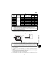
Note: 1. Wire the cables so that the phase sequence is always identical to those of the wiring in 1) and 4).
Connection in wrong phase sequence will damage the power regeneration common converter.
2. Manufactured by J.S.T.
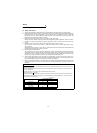
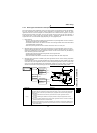
Note: Do not insert the NFB between terminals P - N (P/L+ - P/+, N/L- - N/-).
Do not remove a jumper across terminal P/+ and P1.
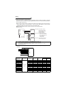
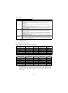
Power
Regeneration
Common
Converter Model
Terminal Name
Terminal
Screw Size
Tightening
Torque N•m
Crimping
Terminals
Cables
mm
2
AWG
FR-CV-7.5K
P/L+, N/L-
M6 4.4 14-6 14 6
FR-CV-11K M6 4.4 14-6 14 6
FR-CV-15K M6 4.4 22-6 22 4
FR-CV-22K M6 4.4
38-S6
(Note 2)
38 2
FR-CV-30K M6 4.4
CB60-S6
(Note 2)
60 1/0
FR-CV-37K M10 14.7 100-10 100 4/0
FR-CV-55K M12 24.5 150-12 150 MCM300
FR-CV-H7.5K M6 4.4 3.5-6 3.5 12
FR-CV-H11K M6 4.4 5.5-6 5.5 10
FR-CV-H15K M6 4.4 14-6 14 6
FR-CV-H22K M6 4.4 22-6 22 4
FR-CV-H30K M6 4.4 22-6 22 4
FR-CV-H37K M8 7.8 38-8 38 2
FR-CV-H55K M8 7.8 60-8 60 1/0
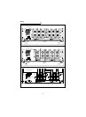
R2/L1
S2/L2
T2/L3
R/L11
S/L21
T/MC1
P/L+
N/L-
R
S
T
R1
S1
P/+
N/-
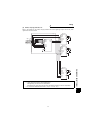
3)
FR-CV
FR-A520
5m (16.40 feet)
maximum