


21
Wiring
INSTALLATION AND WIRING
2
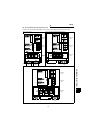
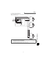
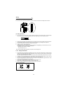
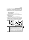
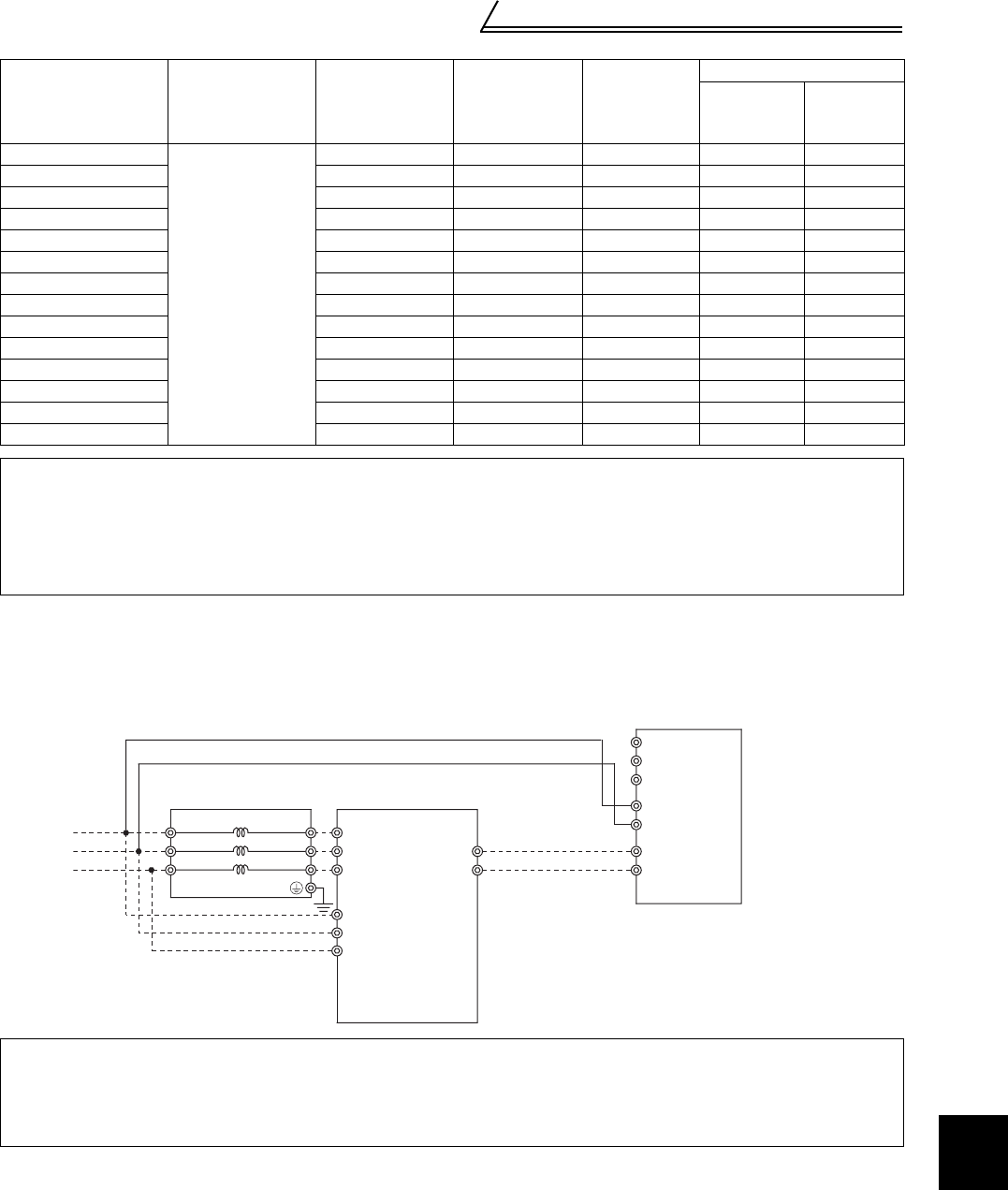
5) Connection of power supply and inverter
When the model used is the one whose control power is input from R1 and S1, control circuit power must be
input to R1 and S1 of the inverter. At this time, remove the jumpers across R-R1, S-S1.
Cable size: 0.75mm
2
to 2mm
2
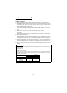
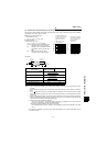
2.2.3 Wiring of the control circuit
(1) Wiring instructions
1) The terminals SD, SE are common to the I/O signals and are isolated from each other. Must not be earthed
(grounded).
2) Shielded or twisted cables must be used for connection to the control circuit terminals, and also run away from
the main and power circuits (including the 200V relay sequence circuit).
3) The input signals to the control circuit are micro currents. When contacts are required, use two or more parallel
micro signal contacts or a twin contact to prevent a contact fault.
4) It is recommended to use the cables of 0.3mm
2
to 0.75mm
2
gauge for connection to the control circuit
terminals.
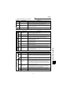
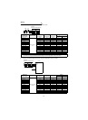
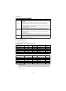
Power
Regeneration
Common
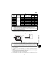
Converter Model
Terminal Name
Terminal
Screw Size
Tightening
Torque N•m
Crimping
Terminals
Cables
mm
2
AWG
FR-CV-7.5K
R/L11, S/L21,
T/MC1
M4 1.5 1.25-4 1.25 16
FR-CV-11K M4 1.5 1.25-4 1.25 16
FR-CV-15K M4 1.5 1.25-4 1.25 16
FR-CV-22K M4 1.5 1.25-4 1.25 16
FR-CV-30K M4 1.5 1.25-4 1.25 16
FR-CV-37K M4 1.5 1.25-4 1.25 16
FR-CV-55K M4 1.5 1.25-4 1.25 16
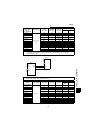
FR-CV-H7.5K M4 1.5 1.25-4 1.25 16
FR-CV-H11K M4 1.5 1.25-4 1.25 16
FR-CV-H15K M4 1.5 1.25-4 1.25 16
FR-CV-H22K M4 1.5 1.25-4 1.25 16
FR-CV-H30K M4 1.5 1.25-4 1.25 16
FR-CV-H37K M4 1.5 1.25-4 1.25 16
FR-CV-H55K M4 1.5 1.25-4 1.25 16
Note: 1. Wire the cables so that the phase sequence of the wiring in 4) is always identical to those of the wiring in
1) and 2).
Connection in wrong phase sequence will damage the power regeneration common converter.
2. To prevent a malfunction due to noise, run the cables away from the main circuit wiring.
3. Running the inverter without connecting terminals R/L11, S/L21 and T/MC1 to the power supply will
damage the power regeneration common converter.
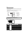
Note: 1. Never connect a power supply to the inverter terminals R, S, T. Accidental connection will damage the
inverter and power regeneration common converter.
2. For the FR-A700, F700, A500, F500 or V500 series, disconnect the jumpers across terminals R-R1, S-
S1 and connect the control power supply to terminals R1, S1. For the FR-E700, D700, E500, S500,
C500 or F500J series, there are no terminals R1, S1 and you need not make the above connection.
R/L11
Dedicated
stand-alone reactor (FR-CVL)
S/L21
T/L31
R2/L12
S2/L22
T2/L32
R2/L1
S2/L2
T2/L3
R/L11
S/L21
T/MC1
P/L+
N/L-
R/L1
S/L2
T/L3
R1/L11
S1/L21
P/
+
N/-
5)
FR-CV
FR-A720
(Note1)
(Note2)