


23
Operation
INSTALLATION AND WIRING
2
2.3 Operation
2.3.1 Pre-operation checks
When installation and wiring are over, make the following checks prior to power-on.
1) Check the wiring for incorrect connection. Especially check that the phase sequence and polarity of the main
circuit wiring are correct.
2) Check for a short circuit caused by wire off-cuts.
3) Check for loose terminal screws.
4) Make sure that the machine is free of damage.
5) Set the parameter values to match the operating machine system environment.
For the FR-A700, F700, A500, F500 or V500 series, set 2 (high power factor converter, power
regeneration common converter) in Pr. 30 "Regenerative function selection".
6) Perform test operation after making sure that safety is ensured if the machine should become out of control.
7) Perform test operation and make sure that the machine operates safely under light load at a low frequency.
After that, start operation.
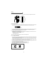
2.3.2 Power-on and operation
Before switching power on, check the following:
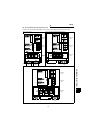
z Installation check
Make sure that the inverter is installed correctly in a proper location. (Refer to page 10.)
• Wiring check
Make sure that the main and control circuits are wired correctly.
Make sure that the options and peripheral devices are selected and connected correctly.
(Refer to page 12.)
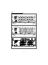
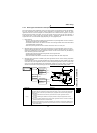
z Switch power on.
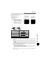
Power-on is complete when the CHARGE lamp is lit correctly and the LED displays correct data.
The LED display gives the following indications at power-on.
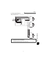
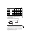
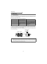
z Start operation.
Turn on the start signal of the inverter. The motor accelerates to a given speed. At this time, the LED display of
the power regeneration common converter shows .
Turn off the start signal of the inverter. The motor decelerates to a stop. The LED display of the power
regeneration common converter shows according to the magnitude of the regenerative energy.
Note: Do not conduct an insulation resistance test with a megger in the power regeneration common converter.
Note:
If the cooling fan has stopped due to a fault, the LED display shows a flickering . (400V class only)
(Refer to page 30.)
Note: When the power regeneration common converter is regenerating power, the dedicated stand-alone reactor
generates sound but it is not a fault.
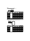
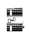
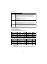
LED
Display
Flicker
Converter
status
Power on
During initialization
During alarm
detection
If the DC voltage is higher than
the input power supply voltage
at power-on, regenerative
operation is performed.
At this time, the bottom
segment flickers.
During normal
operation
(Driving status)
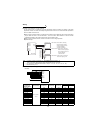
Flicker
LED
Display
Flicker
Converter
status
During driving operation
(During stop)
When the regeneration converter performs
switching operation, the bottom segment flickers.
During regenerative operation