


25
Other wiring
INSTALLATION AND WIRING
2
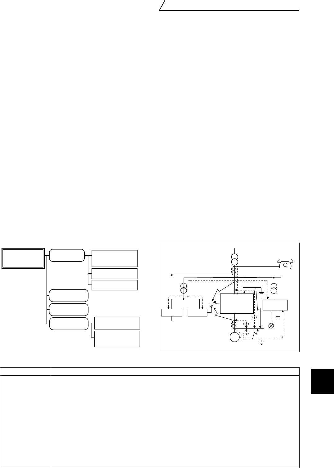
2.4.2 Noise types and reduction techniques
Some noises enter the power regeneration common converter causing it to misoperate and others are radiated by
the power regeneration common converter causing misoperation of peripheral devices. Though the power
regeneration common converter is designed to be insusceptible to noise, it handles low-level signals, so it requires
the following basic measures to be taken. Also, since the inverter chops the output at a high carrier frequency, it
could generate noise. If these noises cause peripheral devices to misoperate, measures should be taken to
suppress the noise. The measures differ slightly depending on noise propagation paths.
1) Basic measures
• Do not run the power cables (I/O cables) and signal cables of the power regeneration common converter in
parallel with each other and do not bundle them.
• Use twisted shielded cables for the detector connection and control signal cables and connect the sheathes
of the shielded cables to terminal SD.
• Ground the power regeneration common converter and inverter, motor, etc. at one point.
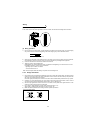
2) Measures against noises which enter and cause misoperation of the power regeneration common converter
When devices which generate many noises (which use magnetic contactors, magnetic brakes, many relays, for
example) are installed near the power regeneration common converter and the inverter may be effected by
noise, the following measures must be taken:
• Provide surge suppressors for devices that generate noise to suppress noise.
• Fit data line filters to signal cables.
• Ground the shields of the detector connection and control signal cables with cable clamp metal.
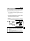
3) Measures against noise which is radiated by the power regeneration common converter causing misoperation
of peripheral devices.
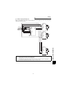
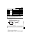
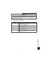
Power regeneration common converter-generated noise is largely classified into those radiated by the cables
connected to the power regeneration common converter and power regeneration common converter main
circuit (I/O), those electromagnetically and electrostatically inducted to the signal cables of the peripheral
devices close to the main circuit power supply, and those transmitted through the power supply cables.
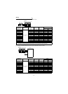
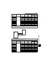
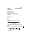
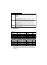
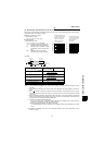
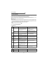
Noise Path Measures
1) 2) 3)
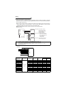
When devices which handle low-level signals and are susceptible to misoperation due to noise (such as
instruments, receivers and sensors) are installed near the power regeneration common converter and
their signal cables are contained in the same panel as the inverter or are run near the power regeneration
common converter, the devices may be affected by air-propagated noises and the following measures
must be taken:
(1) Install easily affected devices as far away as possible from the power regeneration common
converter.
(2) Run easily affected signal cables as far away as possible from the power regeneration common
converter.
(3) Do not run the signal cables and power cables (power regeneration common converter I/O cables) in
parallel with each other and do not bundle them.
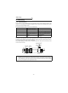
(4) Inset line noise filters into I/O and radio noise filters into input side to suppress cable-radiated noises.
(5) Use shielded cables for signal cables and power cables and run them in individual metal conduits to
reduce further effects.
Air-propagated
noise
Magnetic induction
noise
Static induction
noise
Cable-propagated
noise
Noise directly radiated
by power regeneration
common converter
Noise radiated by
power cables
Noise radiated by
motor cables
Noise propagated
through power cables
Noise from ground
cable due to
leakage current
Path 4), 5)
Path 6)
Path 1)
Path 2)
Path 3)
Path 7
Path 8
Power regeneration
converter generated
noise
Telephone
Sensor
power supply
ReceiverInstrument
Sensor
Motor
IM
1)
2)
2)
3)
8)
7)
5)
4)
6)
7)
3)
Power regeneration
common converter
+
Inverter