


HHXG5 RIDE-ON TROWEL • OPERATION MANUAL — REV. #1 (10/25/10) — PAGE 31
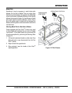
Spare Drive Belt Replacement
To replace a spare drive belt, be prepared to disconnect
the CV-joint from the left-side gearbox. See Figure 21.
1. Place the trowel on suitable supports and observe all
safety precautions.
2. Remove Left-side End Grate and open Left "Clamshell"
3. Remove the three screws that secure the CV-joint to
the left-side gearbox coupler.
4. Once the CV-joint has been separated from the left-side
gearbox, push the CV-joint inward so that a gap exists
between the gearbox and the CV-joint (Figure 21). Slide
the spare V-belt between the gearbox coupler and the
CV-joint. Avoid contaminating the replacement belt with
grease or oil when sliding it between the CV-Joint and
gearbox coupler.
5. Place the spare drive belt inside the drive belt carrier,
and secure the spare belt carrier to the inboard side
of the left gearbox.
6. Install the three screws that secure the CV-joint to the
left-side gearbox coupler.
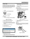
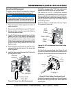
Figure 21. Spare Drive Belt Replacement
NOTICE
It will be necessary to disconnect the CV-Joint from the
left-side gearbox coupler. This means the removal of the
three screws that secure the CV-Joint to the gearbox.
CV Joint Bolt
Left Side
Gearbox
New Spare
Drive Belt
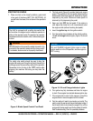
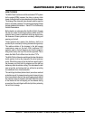
The HHX is equipped with a "CVT" type clutch which
supplies torque to both the left and right gear boxes.
The function of the CVT, (Continuously Variable
Transmission), is to automatically deliver the correct amount
of torque required by the trowel under all load conditions.
This enables the trowel to deliver the necessary torque for
float pan applications and the high rotor speeds required
for burnishing concrete.
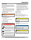
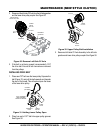
The Driven Pulley is a variable pitch pulley type, (Figure
22) connected by a drive belt.
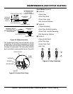
Figure 22. CVT with Variable Pitch Drive Pulley
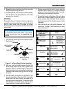
Drive Pulley
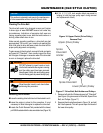
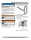
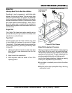
The Drive Pulley uses centrifugal force (Figure 23 and
Figure 24) to create a belt squeeze force transmitted at the
pulley faces. This condition functions as an automatic clutch.
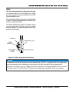
Figure 23. Drive Pulley (Centrifugal Force)
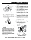
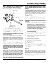
Centrifugal force pushes the roller arms (Figure 24) against
the ramp plate, forcing moveable face toward fixed face
squeezing belt.
CVT
(Drive
Pulley)
Drive V-Belt
Driven
Pulley
C
E
N
T
R
I
F
U
G
A
L
F
O
R
C
E
BELT SQUEEZE
FORCE
FIXED
FACE
VARIABLE
FACE
DRIVE PULLEY
(CVT)
MAINTENANCE (OLD STYLE CLUTCH)