


PAGE 12 — MT55F RAMMER — OPERATION AND PARTS MANUAL — REV. #5 (01/06/12)
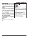
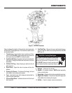
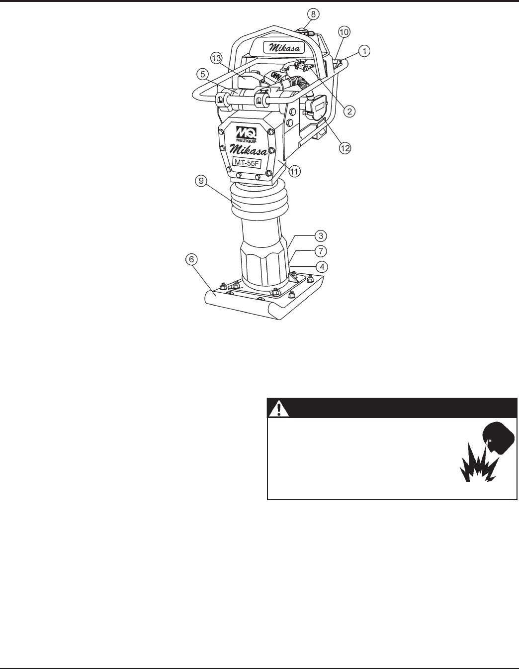
Figure 1 shows the location of the controls and components
for the MT55F Tamping Rammer. The functions of each control
is described below:
L1. A Returned Material Authorization must be approved by Multiquip prior to shipment. A copy of the Authorization must
accompany the shipment to the designated Warehouse. A copy of the original Multiquip invoice to the customer must
also accompany the shipment.
1. Throttle Lever – Used to adjust engine speed (rpm). Move
lever forward
(SLOW)
to reduce engine speed, move lever
back toward operator
(FAST
) to increase speed.
2. Fuel Shut-Off Valve – Supplies fuel from the fuel tank to
the engine. To begin fuel flow move the fuel shut-off valve
downward.
3. Oil Bath Fill Plug – Open this plug to add oil to the oil
bath reservoir.
4. Drain Valve – Open this valve to remove oil from the
bellows.
5. Primary Air Cleaner – Pre-cleans (first stage) dirt and
other debris from entering the engine.
6. Foot– Laminated wood with tempered steel plate for
superior shock absorption.
7. Oil Level Sight Glass – Indicates the level of oil in the oil
bath reservoir.
Figure 1. MT55F Rammer
8. Fuel Tank/Cap – Remove this cap to add unleaded gaso-
line to the fuel tank. Make sure cap is tightened securely. DO
NOT over fill.
9. Bellows – Reservoir for oil bath.
10. Handle – To operate rammer
GRIP
handle assembly
firmly on both sides.
11. Nameplate – Displays information regarding the rammer.
12. Engine Air Cleaner – Prevents dirt (second stage) and
other debris form entering the engine.
13. Muffler – Used to reduce noise and emissions.
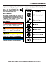
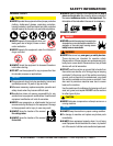
CAUTION - Fueling The Engine
Adding fuel to the tank should be done only
when the engine is stopped and has had an
opportunity to cool down. In the event of a fuel
spill, DO NOT attempt to start the engine until
the fuel residue has been completely wiped up,
COMPONENTS