


Northstar Explorer D310 Installation and Operation Manual
9
Correct installation is critical to the performance of
the unit. It is vital to read this section of the manual
and the documentation that comes with the other
parts before starting installation.
The Explorer D310 can:
Drive external beepers or lights for the alarm.
Send and receive data from other Northstar
instruments connected via NavBus. Settings for
alarms, units, calibration and backlighting are
shared (see section 4-1).
Send and receive NMEA data from other
instruments (see section 4-2).
The unit is waterproof from the front. Protect
the rear of the unit from water, or else water
might enter the breathing hole and damage
the unit. The warranty does not cover damage
caused by moisture or water entering the back
of the unit.
Ensure that any holes that you cut will not
weaken the boat’s structure. If in doubt, consult
a qualified boat builder.
The choice, location, angle and installation
of the transducers is the most critical
part of the installation. If they are not
correct, the unit can not perform at its
designed potential. If in doubt, consult
your Northstar dealer. Plastic through
hull transducers are usually unsuitable for
wood hulls. If in doubt, consult a marine
surveyor or marine engineer.
CAUTION
!
!
CAUTION
DANGER
WARNING
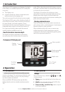
6-1 Installation
Explorer D310 display unit
1 Choose a location for the display unit that is:
Easily seen and protected from damage.
At least 100 mm (4”) from a compass and at
least 500 mm (1.65 ft) from a radio or radar
antenna.
Away from engines, fluorescent lights, and
power inverters.
Accessable from behind; the minimum
clearance required at the back is 50 mm (2”)
(see mounting diagram).
With the back of the unit protected from
moisture.
6 Installation and setup
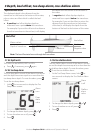
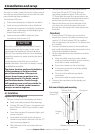
2 The unit must mount on a flat panel which
is less than 20 mm (0.75”) thick. Stick the
mounting template in place. Drill a 50 mm
(2”) fixing hole through the centre hole in the
template. Note that the template allows space
around the unit for the protective cover.
3 Remove the fixing nut from the back of the
unit. Insert the stud at the back of the unit
through the mounting hole. Hand tighten the
fixing nut.
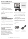
Transducers
1 If the Explorer D310 does not come with a
transducer, choose a suitable transducer (see
section 5-3). If the Explorer D310 is supplied
with a transducer, see section 5-3 to ensure that
it is suitable.
2 Choose a suitable location for the transducer
and install it by following the instructions in the
Transducer Installation manual.
3 Fit the cables between the transducer and the
display unit:
Keep the cable away from other cables,
engines, fluorescent lights, power inverters
and radio or radar transmitters.
Ensure no connectors lay in the bilge.
If necessary, extend the cable by adding
extension cables.
Do not cut the cable on any depth
transducer.
Secure the cable at regular intervals.
4 Connect the transducer to the display unit
connector.
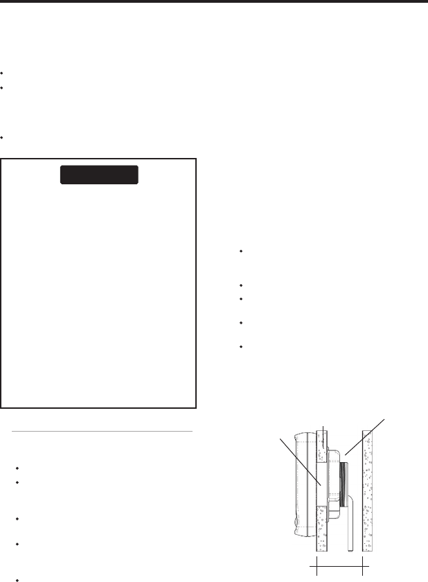
Clearance 50 mm (2”) minimum
20 mm (0.75”)
maximum thickness
Fixing nut
Display
unit
Fixing hole
50 mm (2”)
Side view of display unit mounting
Cables