


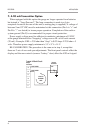
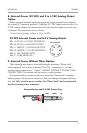
7. 4-20 mA Transmitter Option
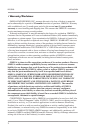
When equipped with this option the gauge no longer operates from batteries
but instead is “Loop Powered”. The loop connection is made to a 6 pin
receptacle located at the rear of the unit (a mating plug is supplied). A voltage of
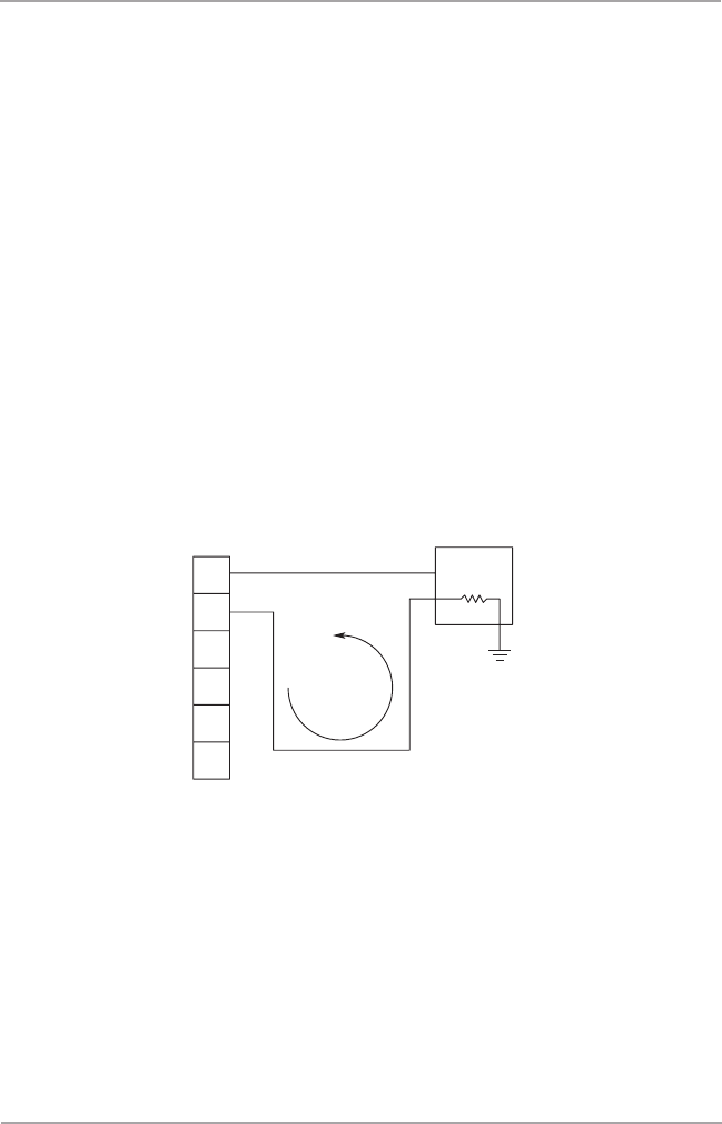
between 9 and 32 VDC must be maintained at this connection (Pin A is “+” and
Pin B is “-” see sketch) to insure proper operation. Completion of the earth or
system ground (Pin F) is recommended for proper circuit protection.
Power supply voltage must be sufficient to maintain a minimum of 9 VDC
at the gauge terminals after “dropping” voltage across RL at full scale current
(20 mA). Example: If RL = 250 ohm then “drop” is 0.02 Amps X 250 ohm = 5
volts. Therefore power supply minimum is 5 V + 9 V = 14 V.
RE-CALIBRATION: The procedure is the same as in step 4, except that
there are 2 sets of zero and span adjustments. The front panel controls affect the
display and the rear controls (remove “battery” door) affect the 4/20 mA signal.
A
B
C
D
– EXCITATION
+ EXCITATION
Gauge
Connector
Typical 4-20 mA Circuit
4-20 mA
CURRENT
LOOP
E
F
Controller
Process
L
R
+Vin
DPG5000 M3366/0606
6