


Calibration Precautions
Install or remove gauge using wrench on hex fitting only.
Do not attempt to tighten or loosen by turning housing or
any other part of the gauge.
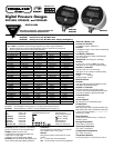
See gauge rear label for pressure range!
Use fittings appropriate for the pressure range of the gauge. The gauge
range is indicated on the rear label and is indicated on the display during
power-up.
Do not apply vacuum to gauges not designed for vacuum operation.
Due to the hardness of 316 stainless steel, it is recommended that a thread
sealant be used to ensure leak-free operation.
NEVER insert objects into the gauge port or blow out with compressed air.
Permanent damage not covered by warranty will result to the sensor.
These products do not contain user serviceable parts. Contact Omega
Engineering for calibration, service, or refurbishment.
1. Calibration Preparation
a. Calibration should only be performed by qualified individuals using
appropriate calibration standards and procedures.
b. The calibration equipment should be at least four times more accurate
than the gauge being calibrated.
c. Remove the screws on the back of the unit and remove cover.
d. It is good practice to install fresh batteries before calibrating battery-
powered gauges.
e. Allow the gauge to equalize to normal room temperature before
calibration.
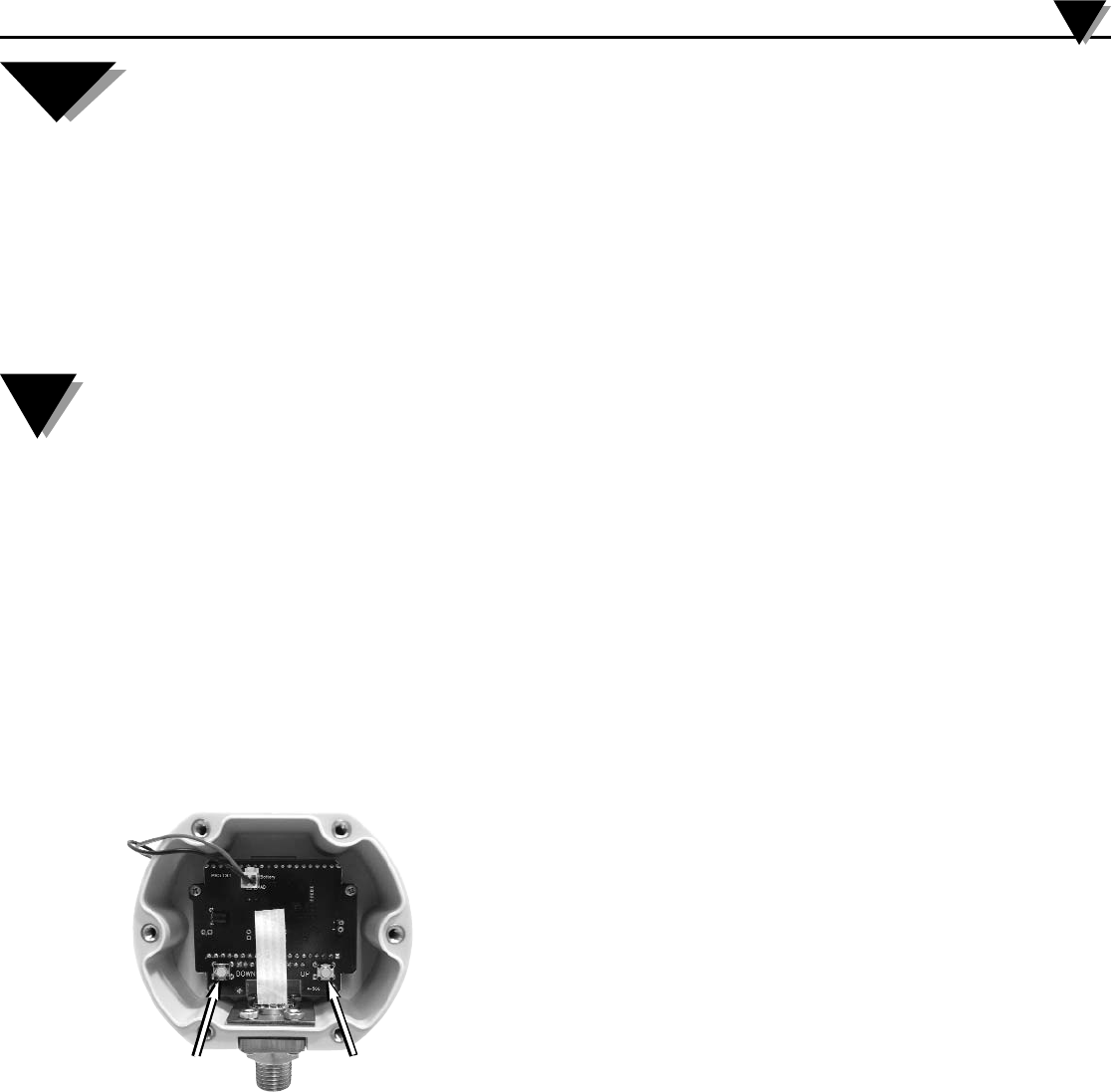
2. Entering the Calibration Mode
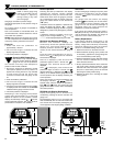
a. Note the locations of the two internal calibration pushbuttons marked
UP and DOWN. These buttons are disabled unless the gauge is in
calibration mode.
b. With the gauge off, press and hold the DOWN calibration button, and
also press the front button to power up the gauge in calibration mode.
3. Calibration Mode Functions
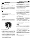
a. The display first indicates the gauge’s full-scale pressure range, tests all
display segments, and then indicates CAL to indicate that the gauge is
in the calibration mode. Release all pushbuttons.
b. The display will then indicate the current pressure reading, updating
approximately 3 times per second. The gauge will remain in the
calibration mode until powered down or reset manually. While in the
calibration mode, the shutoff timer, One Touch Zero (gauge reference
models only), Min/Max (for applicable models) are all disabled, and the
calibration pushbuttons are active.
c. Each press of the UP or DOWN button makes a small correction, which
may not always be indicated on the digital display. Press and hold the
pushbutton for one second or longer to make larger continuous
corrections. The display of the gauge being calibrated is adjusted to
match the calibrator’s setting or readout.
d. If the battery pack is unplugged or the power removed during
calibration, calibration settings will not be saved.
4. Gauge Reference Gauges (3 Points)
a. With the gauge port open to atmosphere, the character display will
alternate between ZERO and CAL. Press the UP and DOWN buttons
to obtain a display indication of zero.
b. Apply full-scale pressure. The character display will alternate between
+SPAN and CAL. Press the UP and DOWN buttons to obtain a
display indication equal to full-scale pressure.
c. Apply 50% of full-scale pressure. The character display will alternate
between +MID and CAL. Press the UP and DOWN buttons to obtain a
display indication equal to 50% of full-scale pressure.
5. Absolute Reference Gauges (3 Points)
a. Apply full vacuum to the gauge. The vacuum pump must be able to
produce a vacuum of 10 microns (0.01 torr or 10 millitorr) or lower. The
character display will alternate between ZERO and CAL. Press the UP
and DOWN buttons to obtain a display indication of zero.
b. Apply full-scale pressure. The character display will alternate between
+SPAN and CAL. Press the UP and DOWN buttons to obtain a
display indication equal to full-scale pressure.
c. Apply 50% of full-scale pressure. The character display will alternate
between +MID and CAL. Press the UP and DOWN buttons to obtain a
display indication equal to 50% of full-scale pressure.
6. Bipolar (±) and –30inHg/15psig Compound Ranges
(5 Points)
a. With the gauge port open to atmosphere, the character display will
alternate between ZERO and CAL. Press the UP and DOWN buttons
to obtain a display indication of zero.
b. Apply full-scale positive pressure. The character display will alternate
between +SPAN and CAL. Press the UP and DOWN buttons to obtain
a display indication equal to full-scale pressure.
c. Apply 50% of full-scale positive pressure. The character display will
alternate between +MID and CAL. Press the UP and DOWN buttons to
obtain a display indication equal to 50% of full-scale pressure.
d. Apply full vacuum. The character display will alternate between -SPAN
and CAL. Press the UP and DOWN buttons to obtain a display
indication equal to the full vacuum reading.
e. Apply 50% of the full-scale vacuum range (for example, –7.4 psi for a
±15 psi gauge). The character display will alternate between -MID and
CAL. Press the UP and DOWN buttons to obtain a display indication
equal to 50% of full-scale vacuum.
7. –30inHg/100psig and –30inHg/200psig Compound
(4 Points)
a. With the gauge port open to atmosphere, the character display will
alternate between ZERO and CAL. Press the UP and DOWN buttons
to obtain a display indication of zero.
b. Apply full-scale positive pressure. The character display will alternate
between +SPAN and CAL. Press the UP and DOWN buttons to obtain
a display indication equal to full-scale pressure.
c. Apply 50% of full-scale positive pressure. The character display will
alternate between +MID and CAL. Press the UP and DOWN buttons to
obtain a display indication equal to 50% of full-scale pressure.
d. Apply full vacuum. The character display will alternate between -SPAN
and CAL. Press the UP and DOWN buttons to obtain a display
indication equal to the full vacuum reading.
8. Exit Calibration Mode and Verify Calibration
a. Battery-powered gauges: Exit the calibration mode and save the
calibration data by pressing and holding the front button until the display
indicates OFF.
b. Verify pressure indications at 0%, 25%, 50%, 75%, and 100% of full
scale.
c. Replace the rear cover and screws, taking care not to pinch the power
leads between the case and the rear cover.
DPG3500, DPG5500, and DPG5600 Series
3
CAUTION:
NOTE:
DOWN UP