


2 HD65 & HD130 STEPPER DRIVES USER GUIDE
Power
Connections
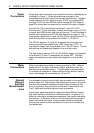
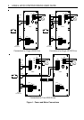
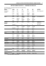
Power and motor connections are made to the drive motherboard as
illustrated in Figure 1. Screw terminals are provided on the
motherboard for the AC input from the mains transformer. Suitable
transformers for the HD drives are type TO132 for a single HD65
and type TO124 for two HD65 drives or a single HD130. Refer to
page 5 for the primary connections for various AC supply voltages.
Connect the 172-volt winding to terminals L1 and L2 on TB1.
Connect one 172-volt secondary to each drive when using a TO124
to power two HD65 drives, and connect the two 172-volt windings in
parallel when operating an HD130 (see diagrams on page 4). If a
three-phase transformer is used, the line-to-line voltage must be 172
volts and connections are made to terminals L1, L2 and L3.
The HD130 requires 115 volts AC to operate its cooling fan and
these connections are made to the "FAN" terminals on TB1. If
required this supply can come directly from 115v AC mains. The fan
connections are commoned together on a multi-axis rack.
The logic supply requires 18-0-18v AC and this supply is connected
to terminals 9, 10 and 11 respectively on socket SK1. The logic
supply connections are also commoned together on a multi-axis
rack.
Motor
Connections
Motor connections are made to screw terminals on TB2. Refer to
pages 6 and 7 for motor connection details, and ensure that the
connections are made correctly. 1.5mm2 cable is recommended.
To reverse the direction of rotation relative to the direction control
input, interchange the connections to 1A and 1B.
General
Wiring &
Earthing
Recommenda
-tions
It is advisable to use a central earth stud mounted on the rack end
plate or close to it. Mains earth, the transformer screen, the rack 0v
bus and the enclosure metalwork should all be connected to this
stud. In particular, the connection to the rack 0v bus should use
1mm
2
cable and should be kept as short as possible.
Input/output signal connections longer than about 500mm should
use wires having a collective or individual screen. In general it is
better to route signal connections separately from power and motor
connections. If the motor leads run in the same trunking as signal
leads, then either the motor or signal leads should be screened.
Connect the screen to the earth stud at one end, and insulate it at
the remote end.