


14 HD65 & HD130 STEPPER DRIVES USER GUIDE
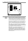
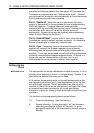
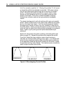
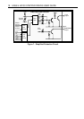
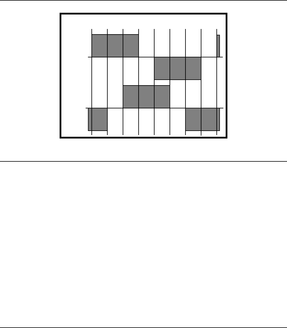
Phase 1
Phase 2
12345678
Step Pulses
9
Figure 5. Current Profile with Square-off
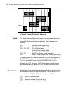
Fuses
The main fuses are fitted on the inside of the motherboard and are
accessible by removing the drive. Ensure that the power has been
turned off before any fuses are inspected. Fuse ratings are as
follows:
FS1 - Fan fuse, 500mA quick acting.
FS2 - Power dump fuse, 2 amp time-delay.
FS3, FS4, FS5 - 172v AC input fuses;
12.5 amp time-delay for HD65,
25 amp time-delay for HD130.
FS6, FS7 - 18v AC input fuses, 1 amp time-delay.
FS8 - 24v DC auxiliary output fuse, 500mA quick acting.
In addition there is an internal fuse within the drive module itself, in
the 240v DC supply between the main capacitor and the switch set.
This is a quick-acting type rated at 10A (HD65), 20A (HD130).
All fuses are 1-1/4 inch type. HBC (high breaking capacity) fuses
are recommended for fuses FS3, FS4, FS5 and the internal drive
fuse.
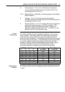
Test Points
At the base of the motherboard are test points which may be used to
monitor motor current using an oscilloscope. The sensitivity is 10.8
amps/volt for the HD65 and 21.5 amps/volt for the HD130.
TP1 - phase 1 current monitor
TP2 - phase 2 current monitor
TP3 - reference voltage (factory use only)
TP4 - 0v (use for scope probe earth lead)