


Parker Hannifin Corporation
Pneumatic Division
Richland, Michigan
www.parker.com/pneumatics
M9
M
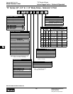
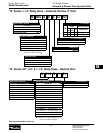
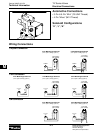
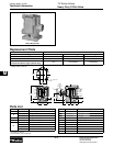
“N” Series Valves
Technical Data
Catalog 0600P-10/USA
Technical Information
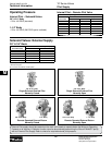
Selection
Although reasonable safety factors are designed
into each speed poppet valve, it is important that
application requirements do not exceed the rated
limitation of the valve. This precaution insures a
sufficient safety factor.
Life Expectancy
Normal multimillion cycle life expectancy of high speed
poppet series valves is based on the use of properly
filtered and lubricated air at room temperature. In
actual laboratory tests, the high speed poppet valves
provide maintenance-free service life in excess of
20,000,000 cycles.
Lubrication
The high speed poppet valves are pre-lubricated to
permit use with non-lubricated air. However, air should
be lubricated to assure maximum seal life.
F442 lubricating oil is recommended. This oil is
specially formulated to provide peak performance and
maximum service life from air-operated equipment.
Other good air line lubricating oils may be used
provided they atomize readily and are of the medium
aniline type. Aniline point range must be between
180°F - 220°F. Viscosity SUS @ 100°F of 140-170.
High aniline oils will shrink seals; low aniline oils will
swell seals, reducing operating life and expectancy.
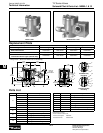
Installation
Valves should be installed with reasonable accessibility
for service whenever possible. Care should be taken
to hold piping length to a minimum and to protect
valves from exposure to extreme heat, dirt and
moisture. Piping should be clean and clear of dirt
and chips. Threads should be the correct size and
undamaged. Pipe joint compound should be used
sparingly and only on pipe threads, never in the valve
body. Care should be taken in installation to avoid
undue strain on valve.
For the small port size options, it is recommended that
an air reservoir is located close to the valve inlet as to
not starve the valve of air pressure.
!
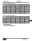
Basic
Valve Size
Inlet
Port Size
Exhaust
Port Size
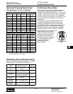
Cv Inlet
to Cylinder
Cv Cylinder
to Exhaust
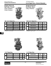
3/8" 3-Way
Normally
Closed
3/8" Pipe 1/2" Pipe 3.6 4.2
1/2" Pipe 1/2" Pipe 3.8 4.3
3/8" 3-Way
Normally
Open
3/8" Pipe 1/2" Pipe 3.6 4.1
1/2" Pipe 1/2" Pipe 3.9 4.5
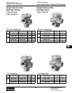
3/4" 3-Way
Normally
Closed
1/2" Pipe 3/4" Pipe 8.2 9.2
3/4" Pipe 1" Pipe 9.3 10.8
3/4" 3-Way
Normally
Open
1/2" Pipe 3/4" Pipe 7.7 6.6
3/4" Pipe 1" Pipe 9.6 11.4
1-1/4"
3-Way
Normally
Closed
1" Pipe 1-1/4" Pipe 19.5 23.5
1-1/4" Pipe 1-1/2" Pipe 23.3 26.9
1-1/2" Pipe 1-1/2" Pipe 23.3 26.9
1-1/4"
3-Way
Normally
Open
1" Pipe 1-1/4" Pipe 20.4 24.8
1-1/4" Pipe 1-1/2" Pipe 25.0 29.1
1-1/2" Pipe 1-1/2" Pipe 26.7 29.9
Operator Type Duty Cycle*
Maximium
Ambient
Temperature
Minimum
Ambient
Temperature
Standard Service Intermittent 0°F (-18°C) 125°F (52°C)
Solenoid Continuous 0°F (-18°C) 100°F (38°C)
Special Service Intermittent 0°F (-18°C) 125°F (52°C)
Solenoid Continuous 0°F (-18°C) 125°F (52°C)
Remote Pilot Not Applicable 0°F (-18°C) 200°F (93°C
Duty cycle =
Time energized
Time energized + time off
× 100% = % Duty Cycle
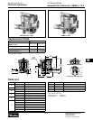
Materials of Construction
Valve Body .....................................................Cast Aluminum
Poppet Assembly ................... Aluminum and Stainless Steel
Pilot Valve .....................Zinc, Stainless Steel, Brass, Copper,
Zinc Plated Steel
Seals ..............................................................................Nitrile
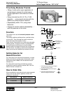
CAUTION: DO NOT RESTRICT THE INLET TO
POPPET VALVES
Restriction of the inlet can starve the air supply to the
pilot section of internally piloted poppet valves and
result in slow shifting or failure of the valve to shift
properly. Always connect the supply line directly to the
inlet of the valve using the full pipe size of the valve
inlet. Never use a quick coupling to connect a poppet
valve to the air supply. On valves with a small inlet
port, use of an upstream surge tank may be required
at lower operating pressures to insure an adequate air
supply and proper operation.
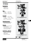
Temperature Rating
Operating Temperature Range:
* Applications with pilot valves energized for ten (10) minutes or longer with a
duty cycle greater than 70% are considered to be continuously energized.
Flow