


6 C1543M-A (7/04)
CIRCUI
T
BOARD
U3
U4
U12
U5
U2
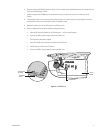
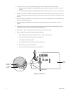
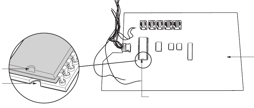
U3 EPROM CHIP
NOTCHED END
OF EPROM
ALIGNMENT
NOTCH
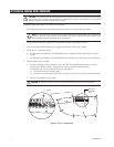
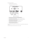
5. Locate DIP switch 7 on the rear of the KBR (refer to Figure 4), and set the DIP switch to the correct position:
• For compatibility with CM9760-CC1 and CM9760-MGR versions 7.80.003 to 7.80.029, set DIP switch 7 to the OFF
position.
• For compatibility with CM9760-CC1 and CM9760-MGR version 8.03.006 or later, set DIP switch 7 to the ON position.
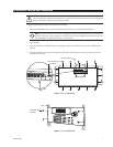
6. Remove the rear panel of the KBR by unscrewing 16 flat head and 4 pan head Phillips screws (5 flat head screws on top
of panel, 5 flat head screws on bottom of panel, 3 flat head screws on each side of panel, and 4 pan head screws on face
of panel).
7. Remove the existing U3 EPROM chip (refer to Figure 6) from its socket using the provided extraction tool. Remove the chip
slowly to avoid damaging the socket.
8. Remove the replacement EPROM chip from the electrostatic bag, and inspect the chip to confirm that the pins are
straight.
9. As illustrated in Figure 6, orient the chip using the alignment notch as a guide. Verify pin-to-socket alignment, and then
carefully press the chip into its socket until the chip is completely seated.
10. Reattach the rear panel of the KBR using the 16 flat head and 4 pan head Phillips screws.
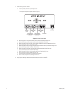
11. Reset the keyboard to factory default settings by doing the following:
a. With the KBR remaining powered off, set DIP switches 1, 2, and 8 to the ON position.
b. Power on the KBR by reconnecting the cable to the COM 1 port.
The Diagnostics mode display appears.
c. Power off the KBR by disconnecting the cable from the COM 1 port.
d. Set DIP switches 1 and 8 to the OFF position.
e. Power on the KBR by reconnecting the cable to the COM 1 port.
Figure 6. U3 EPROM Chip