


3
rubber dust cover from the
SPK
and
MIC
jacks on top of the transceiver. Then insert
the plug of an optional voice-activated
headset with microphone, or an optional
communication headset, into the jacks.
.
±
±±
±
You can also connect an optional mono
earphone to the
SPK
jack. This lets you use
the transceiver's push-to-talk button (
PTT
) to
transmit as usual. Your local RadioShack
store carries a wide selection of suitable
communications headsets, earphones, and
separate components.
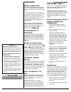
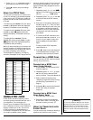
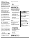
The following schematic diagram shows the
typical wiring for an external mic and
speaker.
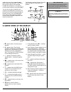
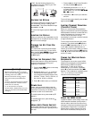
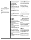
#"37+%-".11-"#6"6*'"&+52.#;
1.
y
— appears when F (function) key is
pressed.
2.
J
JJ
J
— appears when Tone Squelch
(CTCSS) is enabled for transmitting. SQ
appears when Tone Squelch (CTCSS) is
enabled for receiving. TSQ appears
when Tone Squelch (CTCSS) is enabled
for transmitting and receiving.
3.
+
— appears to indicate a positive
repeater offset.
–
indicates a negative
offset.
4.
JEJ
JEJJEJ
JEJ
— appears when a time for the time-
out timer is selected.
5.
7F
7F7F
7F
— appears when Auto Power Off is
enabled.
6.
r
— appears when the SAME alert is
enabled. The icon flashes when the
transceiver is out of range.
7.
í
— indicates the battery strength.
8.
z
— indicates the keypad control is
disabled to prevent accidental setting
changes.
9.
q
— appears when you use the cross
band feature.
10.
o
(Memory Channel Recall) —
appears when you recall a memory
channel.
11. 2-Digit Number below
o
— indicates
memory location number.
12. Sub Frequency Display (appears on the
bottom of the display) — shows the
transmit frequency and other settings. In
the compass mode, the display shows
direction indicator and angles in degree.
13. Signal Strength/Power Meter — shows
the relative signal strength or power
level.
14.
p
— appears and flashes when power
save is on.
15.
C
CC
C
— indicates the output power is
middle.
B
BB
B
indicates the output power is
low. When neither of these appears, the
output power is high.
16. Main Frequency Display (appears in the
middle of the display) — shows the
receive frequency.
17.
7
77
7
— appears when the transceiver tunes
to the air band. (Not shown on this
display.)
.
"%#76+10"
.
Use only microphone and speaker accessories
that do not share a common ground for the
speaker and the microphone. Doing otherwise
might damage the transceiver.
±
±±
±
"016'"
±
±±
±
"
Connecting a headset’s plug to the transceiver’s
SPK jack automatically disconnects the internal
speaker.
1
2
3
4
56 7
8
9
10
11
12
13
14
15
16