


- 6 -
SWRDIM SCAN MEM LOCKENT
AM
FM
RCI−5054
DX
MANR.BEEP
NB/ANL SPLIT
PRG
SHF
CLR GAINRF
USB
LSB
CW
OFF
RF MICPWR VOL
PA
SQ
9
24
15
10
11
16
17
12
18
13
14
19 20
21
21
6
7
8
35
24
23
221
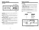
Chapter 4 Operation
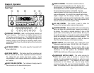
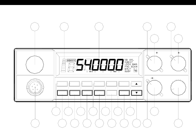
Front Panel
1. FREQUENCY SELECTOR: Used to set the desired transmit and
receive frequency. The frequency is digitally displayed in the
LCD window next to the selector. The FREQUENCY SELECTOR
knob next to the LCD display, allows changing each digit on the
frequency display by first placing the frequency display cursor
(using SHF button) below the desired digit and then turning the
selector knob.
2. RF POWER CONTROL: This control adjust the Transmitter’s RF
power output level.
3. MIC GAIN CONTROL: This feature adjust the microphone gain
for the transmit and PA modes. Experiment with this control for
the setting that will provide best audio quality. Avoid
overmodulation, which causes interference to adjacent stations
and “splatter”.
4. ON/OFF VOLUME CONTROL: Turn clockwise to apply power to
the radio and to set the desired listening level.
- 7 -
5. SQUELCH CONTROL: This control is used to control or
eliminate receiver background noise in the absence of an
incoming signal. For maximum receiver sensitivity, it is
necessary that the control be adjusted only to the point where
the receiver background noise is eliminated. Turn fully
counterclockwise and then slowly clockwise until the receiver
noise just disappears. Any signal to be received must now be
slightly stronger than the average received noise. Further
clockwise rotation will increase the threshold level that a signal
must overcome in order to be heard. Only strong signals will be
heard at a maximum clockwise squelch setting.
6. RF GAIN CONTROL: This control is used to reduce the
receiver's front-end gain when receiving strong signals.
7. CLARIFIER CONTROL: Allows variation of the receive frequency
above and below the selected receive frequency as shown on
the display. This control is intended primarily to tune in SSB
signals when communicating with several stations that may not
be exactly on frequency. It may also be used to optimize AM/FM
signals as described in the operating procedure paragraph. The
clarifier can adjust the receive frequency ±2.5KHz but does not
affect the transmit frequency or the frequency display.
8. MODE SWITCH: This switch allows you to select one of the
following six operating modes: FM, AM, USB, LSB, CW and PA.
9. NB/ANL BUTTON (NB/ANL): The noise blanker (NB) is very
effective in eliminating repetitive impulse noise such as ignition
interference. In the ANL position, the AUTOMATIC NOISE
LIMITER also limits noise at the receiver audio stages.
10. ROGER BEEP BUTTON (R.BEEP): This switch activates the
ROGER BEEP circuit, when its function is selected. When
enabled, the radio automatically transmits an audio tone each
time you release the PTT. This indicates the end of each
transmission so that stations who may be having trouble
receiving will know that you have finished transmitting. This
feature is sometimes used in weak signal conditions or other