


WIRING
WIRING
WARNING: Hazard of Shock and Fire
• Always use proper wire, wire connectors
and fuse/circuit breaker. See Specification
Chart on page 7.
• Secure wire properly.
• Do not connect other appliances to toilet
circuit.
• Make sure power is off before proceeding.
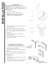
NOTE: Figures shown with installation of Push
Button Switch (#164000).
Refer to manuals included with Toilet Control
(TC*+), Raritime Solid State Timer with Solenoid
(#RTC), or Flush Control (#SWF100+) for wiring
Instructions.
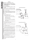
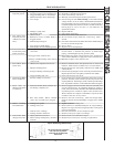
1. Determine proper size wire.
Measure distance from:
• Power source to Push Button Switch.
• Push Button Switch to toilet (and Remote
Intake Pump if used).
• Toilet to ground source.
• Determine total distance of wire needed.
• Select proper size wire from Specification
Chart on page 7.
2. Select proper size fuse/circuit breaker from
Specifications Chart on page 7.
3. Install fuse/circuit breaker in positive line at
source.
4. Connect positive wire from fuse/circuit breaker
to Push Button Switch.
5. Connect wire from Push Button Switch to
orange wire on remote intake pump motor and
positive terminal on discharge pump motor.
NOTE: Pressurized Freshwater Models; connect
wire from Push Button Switch to positive terminal
on discharge pump motor and from Push Button
Switch to one of the wires on water solenoid valve.
The water solenoid valve is not polarity sensitive.
6. Connect wire from battery negative or power
source ground buss to black wire on remote
intake pump motor and negative terminal on
discharge pump motor.
NOTE: Pressurized Freshwater Models; connect
remaining wire from water solenoid valve to
battery negative or power source ground buss.
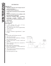
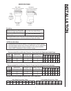
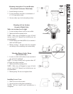
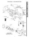
Remote Intake Pump Wiring
Fuse or
Circuit
Breaker
POS
NEG
Push Button
Switch
(#164000)
NEG (-)
NEG (-)
POSNEG
Pressurized Freshwater Wiring
Push Button
Switch
#164000)
Fuse or
Circuit
Breaker
Solenoid
Valve
3 Amp
Fuse
NEG (-)
Black
POS (+)
POS (+)
Orange
POS (+)
12
* Specify Voltage
+ Specify Color