


Installation Guide 5
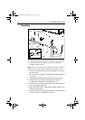
10. Tighten the hose clamps around the bullhorn ram and the rudder
sensor’s barrel.
11. Tighten the starboard bullhorn bolt to secure the U-bracket.
12. Fit and tighten the supplied nut and washer to secure the threaded
rod end of the sensor’s shaft to the U-bracket.
Notes:
1. If there is restricted space below the ram, you can mount the sensor
in front of the ram (not below it).
2. We recommend installing the sensor with its shaft pointing to
starboard. If you cannot install the unit in this orientation, you can fit
it with the shaft pointing to port. If you do this, swap the red and green
connections at the course computer.
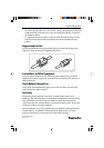
Connecting to the course computer
1. Route the cable to the autopilot or course computer, taking into
account the EMC installation guidelines.
2. Connect to the
RUDDER terminals on the autopilot or course
computer, as described in the owner’s handbook. If required, fit
the spade connectors provided.
Note: To allow for the bullhorn’s movement, leave a loop of cable at
the end of the linear rudder position sensor. If the standard cable is
not long enough, your Raymarine dealer can supply a 10 m (30 ft)
extension cable (part number: D173).
Post installation checks
When you have connected the sensor to your autopilot, pressurize the
steering system (if required).
Note: Contact your steering gear manufacture for advice on this step.
Follow their instructions for re-pressurizing the hydraulic pressure.
When you have done this, check the sensor’s operation as described
in the autopilot owner’s handbook.
81006_3.book Page 5 Tuesday, May 22, 2001 1:03 PM