


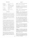
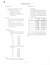

SPECIF'ICATIONS
6-5/16 x
14-I/4
x
Lt)-17/32
1
5
pounds
550
to 1600
KC
-
1.6
to
30
MC
3.5prv
at
20 MC
(6
db
signal-to-
noisc
ratio with 30/s
mocl .
)
6 db
dorvn,
14.5
KC;
60 db
dorvn,
I 25
KC
I
.5 warrs
105 to 125 volts, 60
cps
35 watts
OPERATION
VOLUME
Ciockwise
rotation
of
t]le
Volurne control
knob
turns on
powcl
and increascs
volume.
BAND
SE,LECTOR Rotation
of
the Band
Selector knob
switches antenna and local oscillator
circuits for
the
var-
ious tuning bands.
Index numbers are
located
near
the
knob and at each end of the diai.
TUNING
Rotation
of the Tuning
knob causes
the
main
tuning
indicator
(red)
to move across
the dial
.
BANDSPREAD
Rotation
of
the
Bandspread
loob
affects
a fine tuning
adjustmcnt
of
the reception
frequency.
Nor-
mally
the
indicator
should
be adjusted to the
SET
position.
After
the
approximate
frequency has been tuned
by use
of
the rnain
tuning
lcrob, tl-rc bandspread
adjustrnent
gradually
reduces
the
frequency
for
pinpoint
selection
of
signals,
BFO
Clockwise rotation of
the
BFO
control
turns
on
a
Beat
!-requency
Oscillator
and
increases
the
%
of
modu-
lation
of the IF
signalby tlris oscillator. A
CW signal,
as
usecl
fol single side band
or
code telegraphy purposes,
contains no modulation
and
must be
modulated in
the re-
ceiver
for
proper
reception
(Note:
settings in the
lov/er
range
of this control
may also
improve
reception of
weak
signals
other than
CW type).
ANL
ON
ln
rfie
up
position
this slide
switch
activares
the Automatjc Noise
Limiter circuits designed
to mini-
mize
background noise, static, etc. Operation
in
the
downposition may
benecessary
for reception of
the very
weak
signals since the noise limiter
suppresses
all
low-
er level
signals.
REC
/
STBY
The
receiver
may
be silenced
by moving
this
slide switch to
the STBY
position
witiout actually
turning
off
power
to
the nrbes. Switching
back
to
tfie
REC
position
instantly returns tlle receiver
to normal
opera-
tion
without warTn-up or retuning.
PHONE
This
jack
provides
aconnectionforheadphones
(50
to
1000 ohms)
which
automatically
silences tlre inter-
nal
speaker.
The
Volume control functions as
usual
to
vary the volume
at
tie headphones.
Ditncnsions
Wcight
(net)
Frequency Rangc
Sens itivity
Selectivity
Audio
Orltput
Input Voltage
Power
Consumption
INSTALLATION
Choice of a location for
tlrc
rece iver may bc
subject
to
several
considerations.
Tlrese include the arrangement
oI
lurnitur-c
in thc
roon,
thc
comfort
ancl
convicncc of
tl'rc
listencr,
and acccss to a
good
electrical
ground
and an
outside
antenna. MarT hours
of listening enjoyrnent arc
available
from a
short wave ll:cciver soitis
recommend-
ed
that the selection
of
a location
for
the
DX-75
be
be
carefully
made,
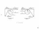
The
antenna for
standard broadcast
is self-contained,
however, an outside
antenna
is
required for
distance
re-
ception
on
the short
wave bands. As
a
general
rule an
outside
antenna
should
be as
high
as
practical
and as long
as
possible (up
to I00
ft.)
for best
reception of
short wave
signals.
The
antenna
should be mounted
away from
power
lines, trees, buildings,
etc.
,
and should
be
attached
to
its
supports
by glass
orceranric insulators. No. 12 to
16 ga.
copper covered steel wire
(uninsulated)
is best
for
both the
antenna and the down lead. A lightening
arrestor
should
be connected
to
the
down
lead for
protection
against
storm
damage.
For additional
information
on
antenna
design
refer to
'A.
R. R.
L. Antenna
Book"
published
by
American
Radio Relay League, or to any
of the
many
other
antenna handbooks
currently
available.
Connect the down
lead from the
antenna
to
the
#2
termi-
nal on
the rear of
the receiver
and connect the
#l
termi-
nal
to a
good
earth ground
such as a water
pipe.
Plug the
power
cord into
a
standard
receptacle
providing
ff7
VAC
power.
t
,l
2