


*
A LIC;NMENT INSTITIJC'f
IONS
Equiptnr:nt
rcquirccl
:
l.
Oscilloscopc
with
calibratcd
vcrtical scalc
2,
RF
Signal
gcncrator-
capablc
of:
a, Oprcratiol
fronr
455
KC to 30 MC
b.
Attenuation
below
lpv
output
c. Modulation
at
I
KC wich
variablc modula-
tron
pcrccnt.rges
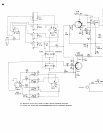
IF Alignnrent
1.
Looscly
couplc a 455
KC, 50/u
modulatcct signal
into
thc
antenna temrinals
(Bancl
Sclector
in
po-
sition
#l)
2.
Corulcct
oscilloscopc to
spcaker
tcrminals
3.
With
signal
gcncr.rtor:'sct to
lowcstu.scablc
sig-
nal
levcl,
1rcak
all
IF-
transfomrers
for
nrexi-
rnunl recovcred audio.
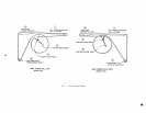
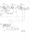
RF Alignmcnt
l.
Prcliminary set
up
a, Bcgi,ruring
with all tr-imnrer
calrecitors
tightly closcd,
o1r:n
thc trinrn)crs
as
fol-
Iows:
C3
I
/4
'I'urn
C4 3/4 Ttrn
C5 l/4
Tuln
C6
7
/8
Turn
Crl 1/'2
1-urn
Clz
l/4'furn
Cl3 l/4'furn
C 14 l,z4
'furn
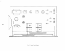
b.
llcginnirg
$itlr ail
slugs at top of fonn ad-
just
as
follotvs:
L2
L3
L4
L6
L7
L8
l5
Turns
22 Turns
l5 Turns
30
Turns
22 Turns
30
Turns
15
'I'urns
NO|E:
These
settings
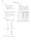
RF Alig'nmcnt
(con't.)
Z. Final
A-lig'nrncnt
ln t-lrc
following
proccdurc,
a signal of
thc spcc-
ilicd
frcqucncy
(ltJ/u
ntoclulat-ctl) is {cd into
thc
antenna tcrminal.
Thc antcnna and
local
oscil-
Iator
tuncd circuits arc adjustcd for
maximum
rccovcrcd
audio, always adjusting thc oscillator
cornlxrncnts first.
Iland
Signal
Frcq.
and
Dial
Sctting
Adjust
for
Maximunr
600 KC
1400
KC
L5, LI
cll,
c3
2
I,8
MC
4.3 MC
L6, L2
ctz, c4
5.0 MC
lr.0 Mc
L7,
L3
c13, c5
4
lr.0
MC
30.0
MC
L8, L4
c
14,
c6
NOTE:
The
atrovc adjustrncnts should bc madc in tlrc
ordcr
shown, anrl
shoukl
bc rcg.:atc-d
scvcral
[inrcs on
caclt band, until
propcr
trackfurg and
calibration
arc ob-
taincd.
7
are approximate
and are
NOT
final-