


Page 4 - 51029073XT/AE
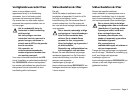
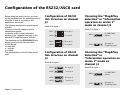
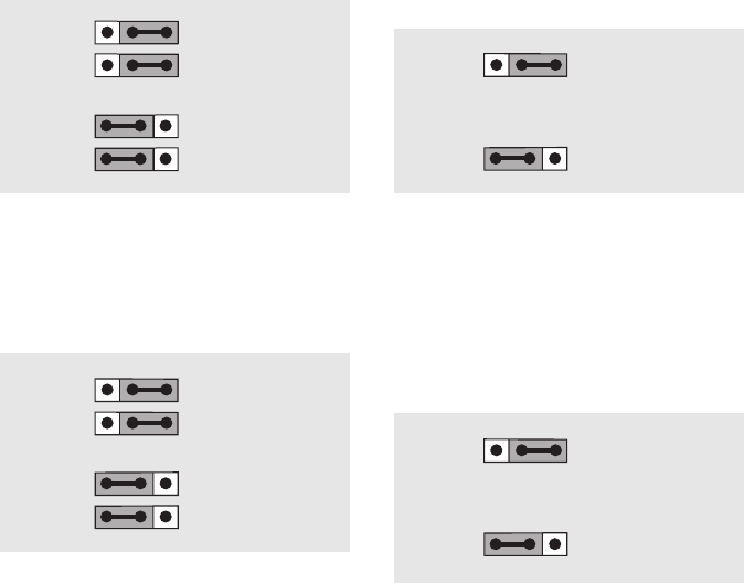
Configuration of RS232
link direction on channel
J4
Detail B of figure 1
Configuration of RS232
link direction on channel
J3
Detail A of figure 1
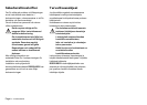
Choosing the "Plug&Play
detection" or "information
operation on mains 2"
mode on channel J3
Detail C of figure 1
Choosing the "Plug&Play
detection" or
"information operation on
mains 2" mode on
channel J4
Detail D of figure 1
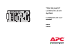
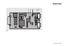
Configuration of the RS232/ASCII card
Before fitting the card in its slot, you must
set the parameters for the operating mode of
channels J3 and J4 according to the
applications connected.
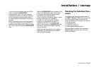
The following configuration operations are
possible:
◗ position of the Rx reception and Tx
transmission signals;
◗ selection of the "contact indication"
function or the "detection and reply to the
Microsoft™ Plug&Play signal" function.
The parameters of the RS232/ASCII links
cannot be set and are fixed as below:
◗ 2400 Bauds;
◗ 8 data bits;
◗ 1 stop bit;
◗ no parity.
The microswitches of the SA1 box are not
used.
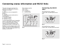
JMP1
JMP2
Rx on pin 3
Tx on pin 2
JMP1
JMP2
Rx on pin 2
Tx on pin 3
JMP4
JMP5
Rx on pin 3
Tx on pin 2
JMP4
JMP5
Rx on pin 2
Tx on pin 3
JMP3
N_ONBYPASS
contact
JMP3
Windows 95
Plug&Play signal
JMP6
N_ONBYPASS
contact
JMP6
Windows 95
Plug&Play signal