


Page 6 - 51029073XT/AE
Fig. 2
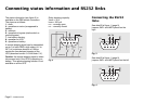
Connecting status information and RS232 links
The status information (see figure 2) is
available on the DB9 socket connectors.
The pins are as follows:
1. earth,
4. operation on mains (as opposed to
battery),
5. common,
6. operation on bypass (static switch or
manual bypass),
7. low battery warning,
8. operation on UPS,
9. operation on battery.
A remote stopping signal can be transmitted
on pin 3 of each DB9: a high status (4 V to
20 V) of a minimum duration of 100 ms
causes the time-delayed stopping of the
UPS (absorbed current: 0.5 mA under 5 V).
Caution: the remote stopping signal is taken
into account only if the UPS is operating on
battery. This remote stopping function is not
available on all the UPS.
Relay breaking capacity:
Vmax = 30 V
lmax = 200 mA
n.o. : normally open,
n.c. : normally closed
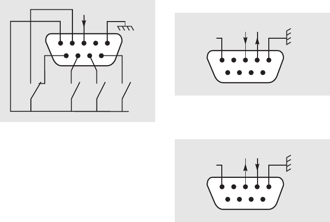
Connecting the RS232
links
See detail B of figure 1 (page 9),
jumpers JMP1 and JMP2 placed on the
right.
Fig. 4
Fig. 3
See detail B of figure 1 (page 9),
jumpers JMP1 and JMP2 placed on the left.
n.o.
n.c.
n.o.
5432
1
9
876
common
n.o. n.o.
5432
1
9
876
RX TX
0V
5432
1
9
876
TX RX
0V