


Owner's Manual
GX1250SPage 8
4 INSTALLATION
4.1 FREQUENCY AND DEVIATION TESTS
FCC regulations require that the transceiver’s deviation and frequency
be tested before initial installation or operation. This test should be
performed by a Certified Marine Technician.
4.2 LOCATION
1. The transceiver can be mounted at any angle. Choose a mounting
location that:
• is far enough from any compass to avoid erroneous compass
reading due to the speaker magnet
• provides protection from sea spray and rain
• provides accessibility to the front panel controls
• allows connection to a power source and an antenna
• has nearby space for installation of a microphone hanger
2. Install the unit in accordance with paragraph 4.3 or 4.4.
In each appears an instruction to connect the power supply and
antenna. Where that appears, the following three steps should be
performed:
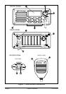
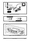
a. At the rear of the transceiver, connect the antenna cable to the
antenna jack. The antenna must have a PL259 connector. RG8 or
RG213 coaxial cable must be used if the antenna is 25 feet or
more from the transceiver. RG58 cable can be used for distances
less than 25 feet.
b. Connect the red power cord to a 13.8 VDC ± 20 % power source.
Connect the black power cord to negative ground. See Figure 3 for
this step .
c. It is advisable to have a Certified Marine Technician check the
power output and the standing wave ratio of the antenna after
installation.