


Manual: 147-082010_HPM-760-Plus-Vacuum-Gauge Page 10 of 16
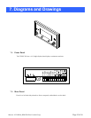
3.5.2. Rear Panel
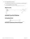
Refer to page 19, 7.1.2 for rear view and specific pin outs and connector arrangements.
AC Input Connector J1
Universal input power 110vac to 220 VAC. No hardware settings required.
J3 Input/Output Connector
Sensor Input (pin 9) Input signal from HPM 760S sensor
Sensor Ground (pin 10) Input ground
Signal output (pin 11) Auxiliary signal output. (0 to +10vdc)
Signal output return (pin 12) Auxiliary signal return
24vdc Output (pin 7) 24vdc Auxiliary output
24vdc Return (pin 8) 24vcd Auxiliary return
SP1 relay contacts (pins 1, 2,3) SP1 relay SPDT contacts. (max)2 amps @ 250vac
SP2 relay contacts (pins 4, 5, 6)) SP2 relay SPDT contacts. (max)2amps @ 250vac
(Either relay will energize when input pressure is less than desired set point).
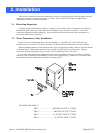
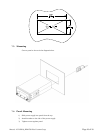
Grounding Considerations
If the THPS-760 is being used in an area with excessive electromagnetic interference (EMI), the power
supply may need to be grounded. This is accomplished by attaching one end of a grounding wire to the
Thumbscrew located at the rear of the THPS 760. The other end should be connected to the 760 sensor
ground. A shielded cable may be utilized.
3.6. Power Supply Relay Set Point Adjustment
The THPS-760 Power Supply has two separate set points with corresponding LED Indicators and
relay contact outputs. Each Relay has option of either normally open or Normally Closed contacts.
1. Ensure 120vac/220vac is supplied to HPS-760 Power Supply. (No switching necessary.)
2. SP1 setting. Depress SP1 set point switch and hold.
(a) Turn the SP1 Potentiometer until the desired set point is.
Displayed on digital display.
(b) Release switch.
3. SP2 setting. Depress SP2 set point switch and hold.
(a) Turn the SP2 Set Point Potentiometer until the desired set point is
Displayed on digital display.
(b) Release switch.
4. With both set point push buttons switches released the digital display will indicate input from
HPM-760 sensor. The SP1/SP2 set point relays will energize when the input is less than the
SP1/SP2 set point. Depressing both set point switches at the same time will result in an
erroneous reading, but will not affect the proper operation of the unit.