


Manual: 147-082010_HPM-760-Plus-Vacuum-Gauge Page 8 of 16
3. Operating Information
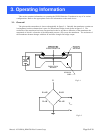
This section contains information on operating the PIEZO Resistive Transducer in any of its various
configurations. Refer to the appropriate section for information on the mode in use.
3.1. General
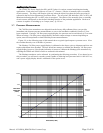
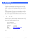
The piezoresistive transducer is shown schematically in figure 3-1. Basically the membrane contains an
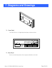
ion implanted resistive element that is part of a Wheatstone bridge circuit shown in figure 3-2. The
underside of the transducer has been evacuated and sealed to produce a deflection of the membrane the
magnitude of which is a function of the differential pressure (ΔP) across the membrane. The resistance of
the membrane element changes with that ΔP and thus changes the bridge output.
V
B
OUT
V
DEPLETION
REGION
PIEZO RESISTOR
DIOXIDE
SILICON
CHIP
R-ΔR
R+
ΔRR-ΔR
R+
ΔR
Fig 3-1
Fig 3-2