


30
English
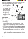
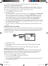
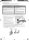
To operate correctly, your radio requires two electrical connections:
x providing it with power from the boat’s electrical system
x connecting a VHF-FM marine antenna to the antenna connector
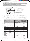
Power Supply Requirements VHF Antenna Requirements
Nominal 13.8 VDC power supply with a
negative ground (9.5 VDC to 15.8 VDC).
Power leads should be kept as short as
possible. A direct connection to the power
supply is ideal.
Minimum of #14 AWG copper wire for
extensions up to 20 feet, 12 AWG wire for
extensions from 20 to 35 feet, or 10 AWG
wire for extensions from 35 to 60 feet.
Male PL-259 connector
50 Ω impedance
Minimum 4 foot, 3 dB rated antenna for
sailboats or 8 foot, 6dB rated antenna for
powerboats
Minimum RG-58 lead-in wire for antenna
leads up to 20 feet, RG-8X for antenna
leads from 20 to 35 feet, or RG-8U for
antenna leads from 35 to 60 feet.
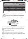
1. Connect the BLACK wire of the power cable to the NEGATIVE (-) side of your power
source.
2. Connect the RED wire of the power cable to
the POSITIVE (+) side of your power source.
3. NOTE: To extend the life of the radio,
use waterproof tape to seal electrical
connections.
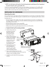
4. Install your antenna according to the
manufacturer’s instructions.
5. If necessary, consult the FCC guidelines for
antenna separation. See Antenna Selection
and Installation on page 47 for more
details. (In summary, the FCC recommends
that antennas up to 3 dB be installed a minimum of 3 feet from any occupied location;
antennas over 3 dB should be installed at least 6 feet away.)
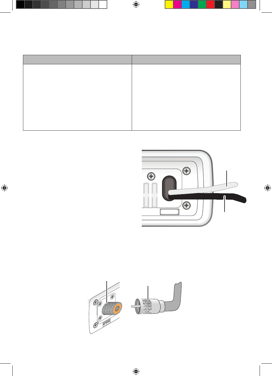
6. Connect the PL-259 connector from the antenna lead-in wires to the SO238 connector
labeled
ANTENNA
on the back of your radio.
13.8V DC
Black wire
(-)
Red wire
(+)
Radio connector,
SO238 (female
PL-259)
Antenna lead-in
connector,
male PL-259
UM380_20101221.indd 30 4/13/2011 11:25:17 AM