


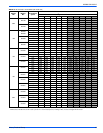
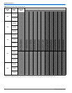
819288-UIM-A-0212
Unitary Products Group 3
DOWNFLOW AND HORIZONTAL CONVERSION
These air handler units are supplied ready to be installed in a upflow,
downflow and left or right hand horizontal position.
If the unit is to be installed with an evaporator coil, refer to Figure 1 for
unit positioning information.
AIR HANDLER AND COIL UPFLOW AND
HORIZONTAL
1. Apply neoprene gasket to top of coil casing.
2. Position blower casing over coil opening.
3. Attach tie plate to casings of air handler and coil using screws.
4. Remove blower access panel and coil filter door.
5. Disconnect wiring to blower motor. *Note location of wires as these
will be reconnected in a later step.
6. Remove blower motor and housing.
7. Fasten duct flanges of coil to duct flanges of air handler with
screws. See Figure 1.
8. Secure base of air handler to top of coil using screws.
9. Locate 2” wide foam gasket.
10. On the interior of the air handler/coil attachment point, apply foam
gasket over duct flanges on the sides and back.
11. Reinstall blower motor and housing by reversing the process in
Steps 3 and 4.
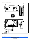
12. Complete electrical and blower speed connections as outlined in
other sections of this document.
13. Reposition and replace blower access panel.
AIR HANDLER AND COIL DOWNFLOW
1. Position blower casing over duct connection and secure such that
the supply air end of the blower is down.
2. Apply neoprene gasket to return-air side of air handler.
3. Place coil casing over blower return opening.
4. Attach tie plate to casings of air handler and coil using screws.
5. Remove blower access panel and coil filter door.
6. Disconnect wiring to blower motor.
*Note location of wires as these will be reconnected in a later step.
7. Remove blower motor and housing.
8. Fasten duct flanges of coil to base of air handler with screws. See
Figure 1.
9. Secure base of air handler to base of coil using screws.
10. Locate 2” wide foam gasket.
11. On the interior of the air handler/coil attachment point, apply foam
gasket over duct flanges on the sides and back.
12. Reinstall blower motor and housing by reversing the process in
Steps 3 and 4.
13. Complete electrical and blower speed connections as outlined in
other sections of this document.
14. Reposition and replace blower access panel.
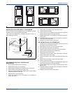
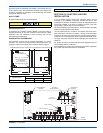
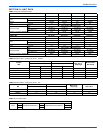
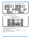
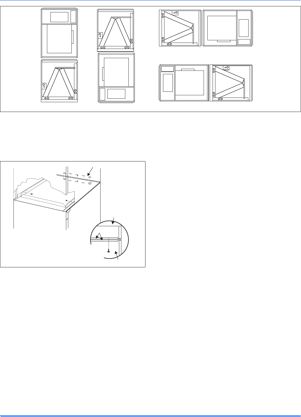
FIGURE 1: Typical Installation with MC Multi-Position Coils
UPFLOW
DOWNFLOW
HORIZONTALRIGHT
HORIZONTALLEFT
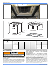
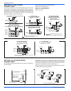
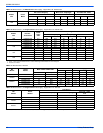
FIGURE 2: Coil and Air Handler Attachment Details
TIE PLATE
COIL
AIR HANDLER
COIL
TOP PLATE
AIR HANDLER
DOWNFLOW
APPLICATION
UPFLOW & HORIZONTAL
APPLICATIONS