


819288-UIM-A-0212
Unitary Products Group 5
Duct work should be fabricated and installed in accordance with local
and/or national codes. This includes the standards of the National Fire
Protection Association for Installation of Air-Conditioning and Ventilat-
ing Systems, NFPA No. 90B.
AIR FILTERS
Air filters and filter racks must be field supplied.
.
SUSPENSION KITS
A suspension kit is available. Models 1BH0601 (unit size 018-060) is
designed specifically for the units contained in this instruction (upflow
application only). For installation of these accessory kits, see the
instructions packed with the kit.
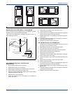
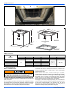
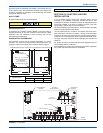
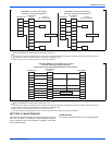
HORIZONTAL SUSPENSION
For suspension of these units in horizontal applications, it is recom-
mended to use angle steel support brackets with threaded rods, sup-
porting the units from the bottom, at the locations shown in Figure 4.
SECTION IV: ELECTRIC HEATER
INSTALLATION
If the air handler requires electric heat, install the electric heat kit
according to the installation instructions included with the kit. After
installing the kit, mark the air handler nameplate to designate the heater
kit that was installed. If no heater is installed, mark the name plate
appropriately to indicate that no heat kit is installed.
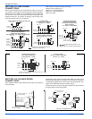
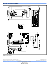
The HEAT ENABLE jumper (See Figure 5) must be moved to the HEAT
position to enable operation of the heater.
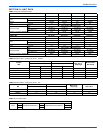
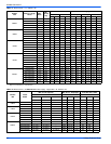
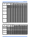
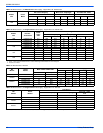
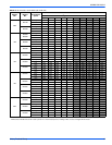
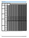
Use only 4HK heater kits, as listed on Air Handler name plate and in
these Instructions. Use data from Tables 11 through 18 for information
on required minimum motor speed tap to be used for heating operation,
maximum over-current protection device required and minimum electri-
cal supply wiring size required for listed combination of Air Handler and
Heater Kit.
For Upflow, Downflow and Horizontal right hand applications the kits
can be installed without modification.
Field modification is required for Horizontal left-hand airflow application
only. Follow instructions with heater for modification.
Equipment should never be operated without filters.
Units
(Nominal Tons)
Dimension
WW XX YY
1-1/2 - 3 Ton 16” 48” 22”
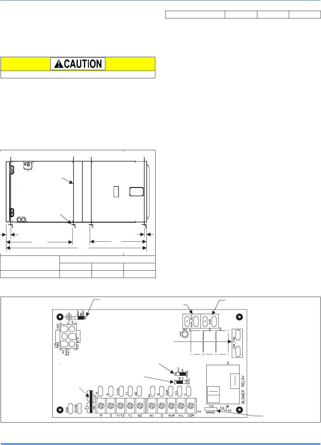
FIGURE 5: Typical Horizontal Installation
WW
XX
SUSPENSION SUPPORT LOCATIONSFOR HORIZONTALAPPLICATIONS
2
1-1/2
MIN. 1-1/2” x 1-1/2”Angle
Recommended length
26” minimum
with 2” clearance on
both sides ofAir Handler
MIN. 3/8”
THREADED ROD
YY
3-1/2 - 5 Ton 24” 53” - 58” 22”
FIGURE 5: Typical Horizontal Installation
FIGURE 6: Control Board
HEATENABLE
JUMPER
HUM OUT
RELAYOUTPUT
EAC RELAY
OUTPUT
LOW FAN
RELAYOUTPUT
SPARE
JUMPER
HUM STATJUMPER
MODE JUMPER
FUSE