


iv
TABLE OF CONTENTS
Introduction . . . . . . . . . . . . . . . . . . . . . . . . . . . . . . . . . . . . . . . . . . . . . . . . . . . 1
Controls, Indicators and Connectors . . . . . . . . . . . . . . . . . . . . . . . . . . . . . . . . . . 1
How This Inverter Works . . . . . . . . . . . . . . . . . . . . . . . . . . . . . . . . . . . . . . . . . . 2
Principle of Operation . . . . . . . . . . . . . . . . . . . . . . . . . . . . . . . . . . . . . . . . . . 2
The Power Inverter Output Waveform . . . . . . . . . . . . . . . . . . . . . . . . . . . . . . . 2
Protective Features of the Inverter . . . . . . . . . . . . . . . . . . . . . . . . . . . . . . . . . . . . 3
Installation and Operating Instructions . . . . . . . . . . . . . . . . . . . . . . . . . . . . . . . . 3
Power Source Requirements . . . . . . . . . . . . . . . . . . . . . . . . . . . . . . . . . . . . . . 3
Connection to a Power Source . . . . . . . . . . . . . . . . . . . . . . . . . . . . . . . . . . . . 4
Connection to Load . . . . . . . . . . . . . . . . . . . . . . . . . . . . . . . . . . . . . . . . . . . 5
Placement of the Inverter . . . . . . . . . . . . . . . . . . . . . . . . . . . . . . . . . . . . . . . . 5
Operating Tips . . . . . . . . . . . . . . . . . . . . . . . . . . . . . . . . . . . . . . . . . . . . . . . 6
Care and Maintenance . . . . . . . . . . . . . . . . . . . . . . . . . . . . . . . . . . . . . . . . . . 7
Storage . . . . . . . . . . . . . . . . . . . . . . . . . . . . . . . . . . . . . . . . . . . . . . . . . . . . 7
Maintenance . . . . . . . . . . . . . . . . . . . . . . . . . . . . . . . . . . . . . . . . . . . . . . . . 7
Fuse Replacement . . . . . . . . . . . . . . . . . . . . . . . . . . . . . . . . . . . . . . . . . . . . . 7
Troubleshooting . . . . . . . . . . . . . . . . . . . . . . . . . . . . . . . . . . . . . . . . . . . . . . . . 7
Common Audio/Visual Problems . . . . . . . . . . . . . . . . . . . . . . . . . . . . . . . . . . 7
Fault Protection Code and Troubleshooting Guide . . . . . . . . . . . . . . . . . . . . . . 8
Specifications . . . . . . . . . . . . . . . . . . . . . . . . . . . . . . . . . . . . . . . . . . . . . . . . . 8
1
INTRODUCTION
Your new
VEC1043 750 Watt Power Inverter Vehicle Power System
is one
in a series of the most advanced DC to AC inverters available. With proper care and
appropriate usage, it will give you years of dependable service in your car, truck, RV
or boat.
The
VEC1043
supplies 750 watts of continuous power, in the form of two standard
North American household outlets that are ready to deliver 115 volt AC power
whenever and wherever you need it! The heavy-duty inverter has enough power to
run most household or electronic appliances. It also comes equipped with battery
clips to handle higher amperage/load applications, such as: power tools, stereo
amplifiers, vacuums, etc. Added safety features include automatic shutdown and a
low battery alarm to prevent damage to your battery.
This Vector Power Inverter is configured with the latest Soft Start Technology (SST).
Before introduction of Soft-Start, high start-up currents from large inductive loads could
shut down the inverter. Soft Start improves inverter operation. Three major features
incorporated in SST include: First, gradual voltage ramp-up during inverter start-up.
This eliminates failed cold starts under load. Second, output that momentarily dips in
voltage and quickly recovers to allow large motorized loads to start. This eliminates
almost all shutdowns from momentary overloads. Last, the inverter needs to be turned
off then turned on once the overload that caused the inverter shutdown is removed.
This power inverter also incorporates a new cooling technology that directly benefits
our customers. The new design more efficiently cools the power transistors, and
combined with Soft Start, dramatically increases reliability and the life of the product.
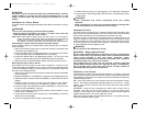
CONTROLS, INDICATORS AND CONNECTORS
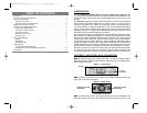
details the front panel, featuring the unit’s 115 volt AC Outlets. Power is
supplied through two standard North American outlets that can accommodate either
two- or three-pin AC plugs.
Figure 1 Front Panel
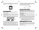
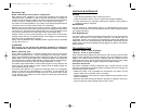
shows the back panel of the inverter, where the DC Power Connections and
high speed cooling fan are located.
Figure 2 Back Panel
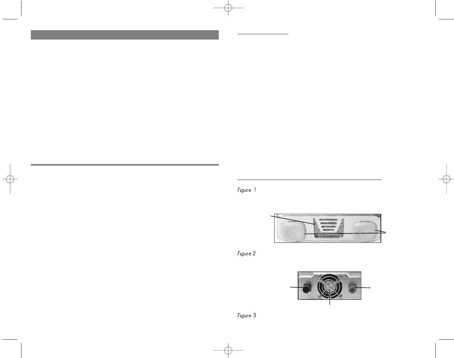
details the top panel of the inverter, featuring the ON/OFF Pushbutton and
three LED indicators. The green LED indicates power and proper operation of the
POSITIVE DC POWER
CONNECTION
NEGATIVE DC POWER
CONNECTION
HIGH SPEED COOLING FAN
115 VOLT
AC OUTLETS
AIR VENT
VEC1043_ManualEN_091505 1/17/06 5:49 PM Page iv