


5
9. Test the inverter by turning it on and plugging in a 100 watt lamp or equipment.
10. If the inverter is not operating properly, then refer to the “Troubleshooting” section
of this manual.
CAUTIONS
• Loose connectors may cause overheated wires and melted
insulation.
• Check to make sure you have not reversed the polarity. Damage due
to reversed polarity is not covered by our warranty.
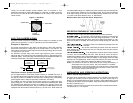
Connection To Load
The Power Inverter is equipped with a standard North American three-prong type
outlet. Plug the cord from the equipment you wish to operate into the AC outlet. Make
sure the load requirement of your equipment does not exceed 750 watts.
The Power Inverter is engineered to be connected directly to standard electrical and
electronic equipment in the manner described above. Do not connect the Power
Inverter to household or RV AC distribution wiring. Do not connect the Power Inverter
to any AC load circuit in which the neutral conductor is connected to ground (earth)
or to the NEGATIVE of the DC (battery) source.
WARNING
Do not connect to AC distribution wiring!
CAUTION – Rechargeable Devices
Certain rechargeable devices do not operate well from a modified sine
wave inverter. They only operate properly from a standard household
outlet which provides a pure sine wave. Therefore, Vector
recommends that these types of devices be operated from a standard
household outlet only, not from the inverter.
This problem does not occur with the majority of battery-operated
devices. Most of these devices use a separate charger or transformer
that is plugged into an AC outlet. This inverter is easily capable of
operating most chargers and transformers.
Placement of the Inverter
For best operating results, the inverter should be placed on a flat surface, such as the
ground, car floor or seat, or other solid surface. A power cord has been provided for
easy positioning of the inverter. The inverter should only be operated in locations that
meet the following criteria:
DRY – Do not allow water and/or other liquids to come into contact with the inverter.
COOL — Surrounding air temperature should be between –0°C and 40°C — ideally
between 15°C and 25°C (60-80°F). Keep the inverter away from direct sunlight,
when possible.
VENTILATED – Keep the area surrounding the inverter clear to ensure free air
circulation around the unit. Do not place items on or over the inverter during
operation. A fan is helpful if the inverter is operating at maximum power outputs for
extended periods of time. The unit will restart after it cools.
SAFE – Do not use the inverter near flammable materials or in any locations that may
accumulate flammable fumes or gases.
4
CAUTION
The Power Inverter must be connected only to batteries with a nominal
output voltage of 12 volts. The unit will not operate from a 6 volt
battery and will sustain permanent damage if connected to a 24 volt
battery.
Connection to a Power Source
The Power Inverter comes equipped with battery clip cables for connection to a power
source.
CAUTIONS
• Do not use with positive ground electrical systems.
• Reverse polarity connection will result in a blown fuse and may
cause permanent damage to the inverter.
Notes:
Most vehicle accessory outlet circuits have fuses rated at 15 to 20 amps or
greater. To operate at full wattage, either use the battery clip cable (supplied)
or directly wire to the power source with user-supplied wire and fuse.
The majority of modern automobiles, RVs and trucks are negative ground.
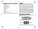
Connecting to a Power Source Using the Provided Cables
Use the provided cables and connect the Power Inverter directly to the 12 volt power
source as follows:
1. Make sure the Power Inverter power is turned OFF and that no flammable fumes
are present in the installation area.
2. Connect the RED cable to the RED post marked (+) on the back of the inverter.
Connect the battery clip to the POSITIVE terminal of the battery.
3. Connect the BLACK cable to the BLACK post marked (–) on the back of the
inverter. Connect the battery clip to the NEGATIVE terminal of the battery.
4. Make sure that all connections between battery clips and terminals are secure.
Direct Hardwiring to Power Source
Use #8 AWG wire if the inverter to power source connection is 4 feet or less. For
longer cable lengths use #6 AWG wire (to 10 feet). In either case, protect the positive
(+) wire from shorts by installing a 150-200 amp fuse or circuit breaker close to the
DC power source (battery) terminal.
1. Check to be sure the inverter’s power switch is turned OFF and that no flammable
fumes are present.
2. Identify the POSITIVE (+) and NEGATIVE (–) DC power source (battery) terminals.
3. Install a fuse holder or breaker close to the POSITIVE (+) terminal of the DC source
(battery).
4. Connect a length of wire on one side of the fuse holder or circuit breaker.
Connect the other end of the wire to the POSITIVE (+) terminal of the inverter.
5. Connect a length of wire between the inverter’s NEGATIVE (–) terminal and the
DC power source NEGATIVE (–-) terminal.
6. Connect a short length of wire to the other terminal of the fuse holder or circuit
breaker. Mark it “POSITIVE” or “+”.
7. Connect the free end of the fuse or breaker wire to the POSITIVE (+) terminal of
the DC power source (battery).
8. Insert a fuse appropriate to the inverter in the fuse holder.
VEC1043_ManualEN_091505 1/17/06 5:49 PM Page 4